

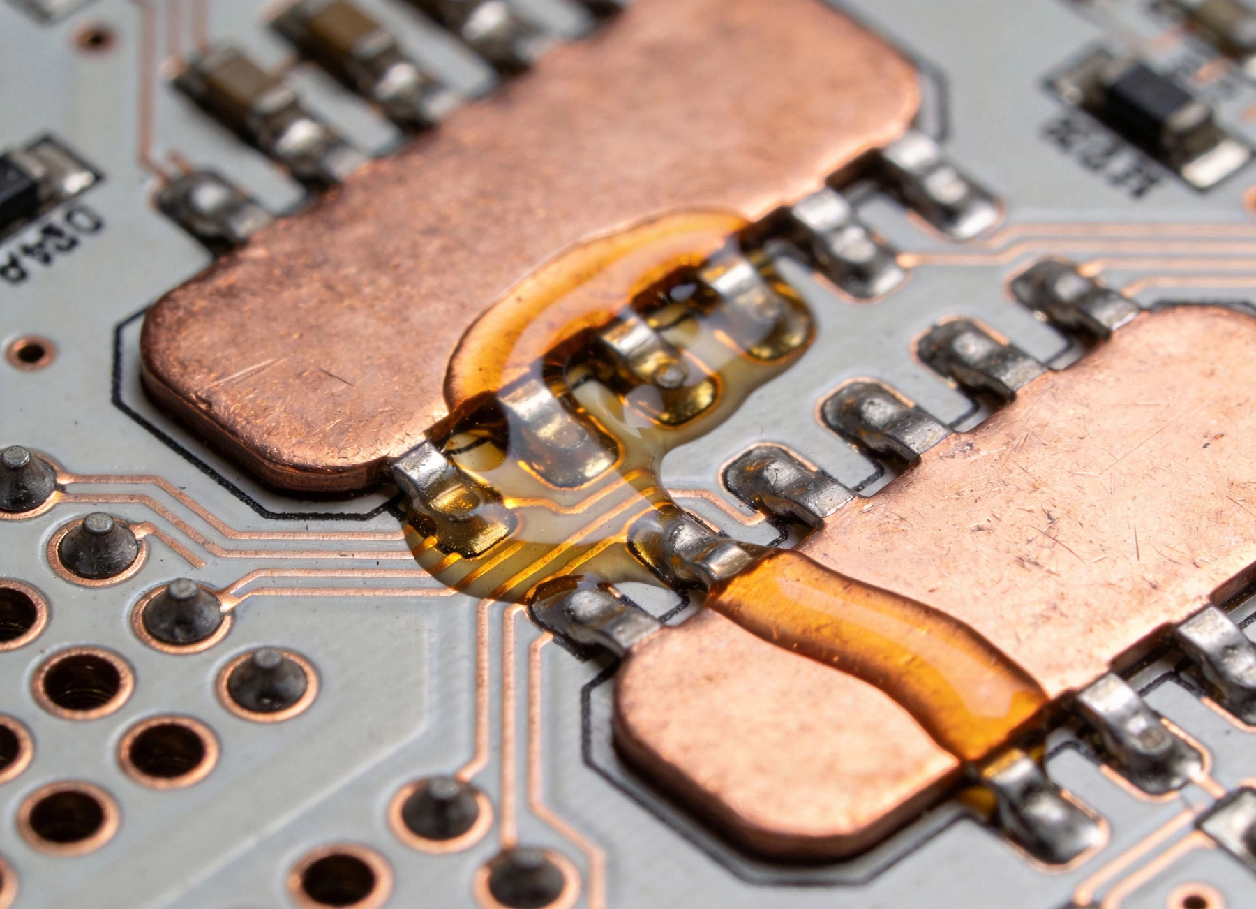
Power electronics push current levels that consumer gadgets never encounter. When amperage climbs past 5A, 10A, or even 100A, the humble solder joint becomes a critical design element. Get it wrong, and you face field failures, thermal runaway, or ...
https://www.high-current-pcb.com/high-current-pcb-materials-standards/high-current-pcb-solder-joints-wave-soldering-vs-selective-soldering/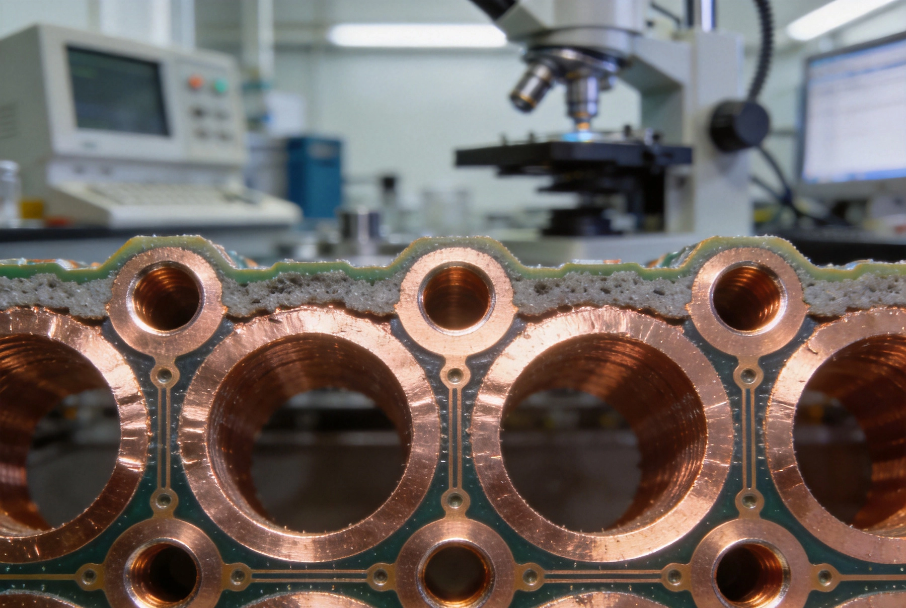
Via plating thickness represents one of the most consequential specifications in high current PCB design. When engineers design power distribution networks for automotive motor drives, industrial motor controllers, or server power supplies, the cop...
https://www.high-current-pcb.com/high-current-pcb-dfm-tips/high-current-pcb-via-plating-1mil-vs-2mil-thickness-reliability-test/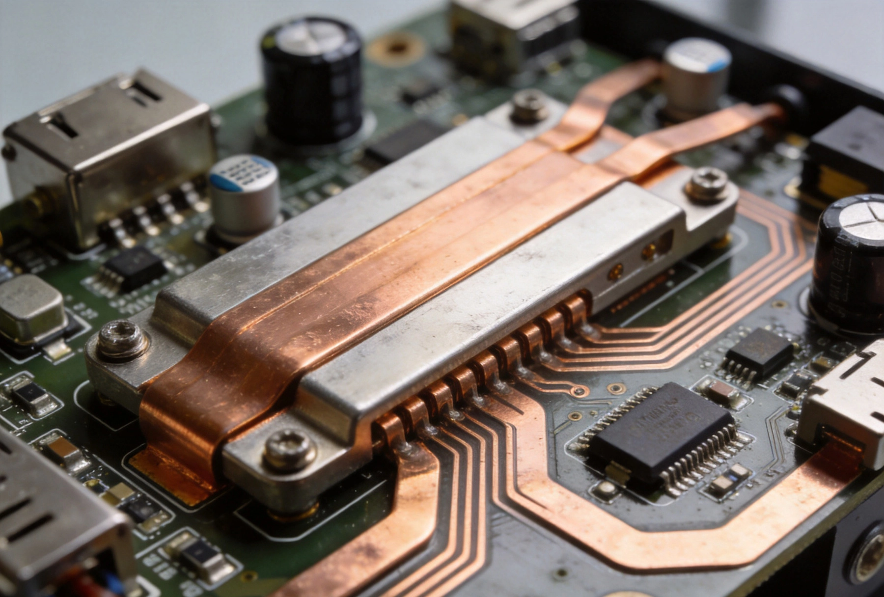
The rapid growth of electric vehicle adoption has created unprecedented demand for reliable, high-power charging infrastructure. At the heart of every EV charging station lies a sophisticated power electronics system, with printed circuit boards se...
https://www.high-current-pcb.com/high-current-pcb-thermal-design/high-current-pcb-design-for-electric-vehicle-charging-stations/