

Rigid-flex PCBs solve real packaging problems. They eliminate connectors, reduce weight, and enable three-dimensional packaging that rigid boards alone can't achieve. But when you need to carry significant current—power for motors, battery systems, or high-wattage loads—through the flexible portion of a rigid-flex assembly, you encounter challenges that don't exist in purely rigid designs.
The fundamental tension is this: the flex section needs to bend, and bending imposes constraints on Copper Weight, Trace Geometry, and reliability that directly conflict with the requirements for high Current Carrying Capacity. Resolving this tension requires understanding what's actually happening at the bend and designing accordingly, rather than applying rigid-board thinking to a flexible section.
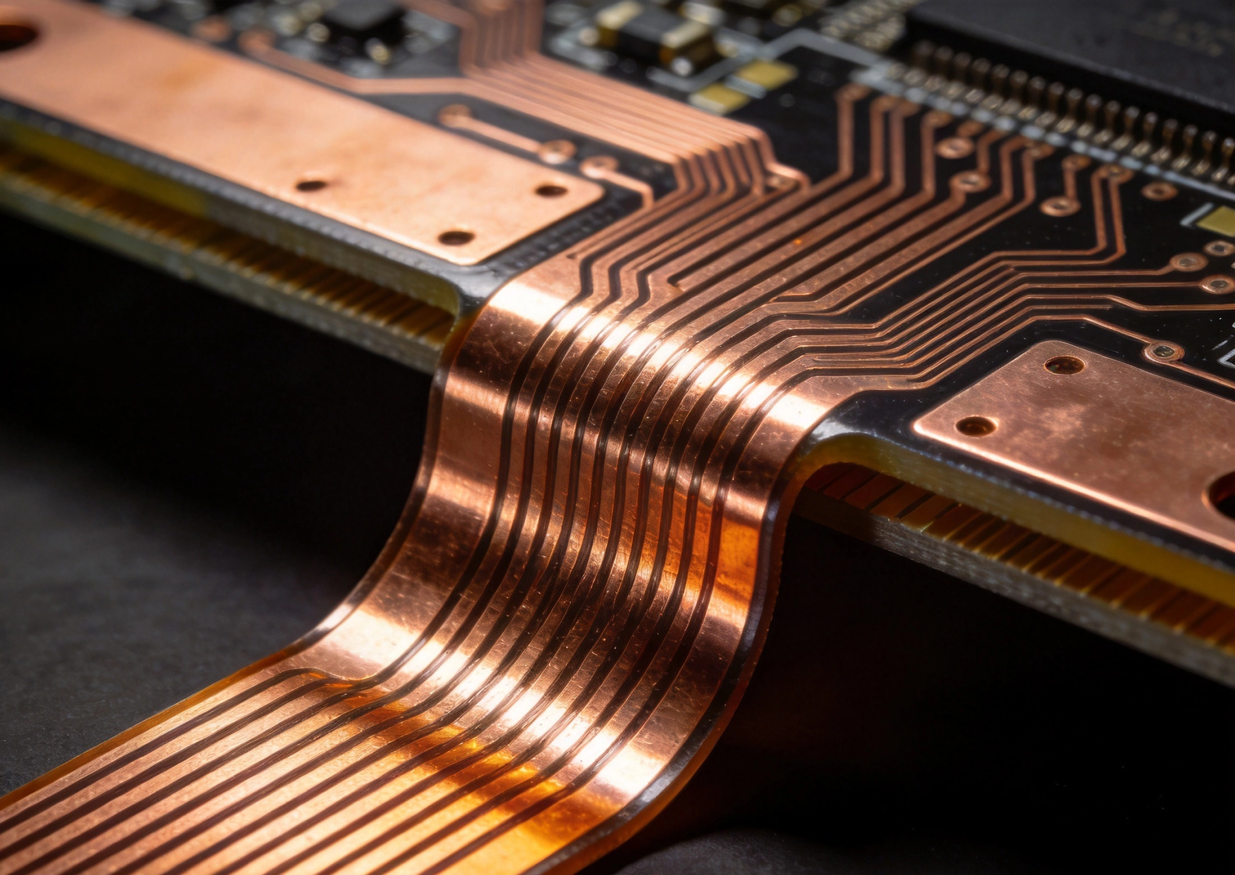
In a rigid section of a PCB, Heavy Copper—2 ounces, 3 ounces, even 6 ounces per square foot—carries High Current with acceptable temperature rise. The substrate supports the copper mechanically, and the copper doesn't need to flex. This is straightforward Power Distribution.
Flex zones are different. The copper in a flexible section must survive repeated bending or a static bend without cracking, delaminating from the substrate, or developing resistive increases that indicate fatigue failure. These reliability requirements limit Copper Weight in flex areas in ways that don't apply to rigid sections.
Standard flex designs typically use 0.5 ounce or 1 ounce copper in the flexible layers. This copper is deposited as rolled annealed copper rather than electrodeposited copper—rolled copper has a grain structure oriented along the length of the trace, which provides significantly better fatigue resistance under bending. But even rolled copper has limits, and those limits are reached more quickly as copper weight increases.
Heavier copper in flex areas means reduced bend cycle life. A 1-ounce flex layer might survive millions of bend cycles at a reasonable radius. A 2-ounce flex layer at the same radius might survive only thousands. For applications where the flex section bends repeatedly—like a hinge in a laptop or a moving sensor—this difference is critical.
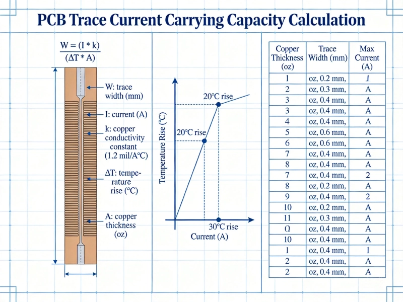
Current Carrying Capacity in a flex trace depends on trace width, Copper Thickness, and allowable temperature rise—the same parameters that govern rigid board traces. But flex traces require additional derating considerations that rigid traces don't.
First, the allowable temperature rise is typically lower in a flex section. Polyimide flex substrates can withstand higher temperatures than standard FR-4, but the adhesive layers bonding flex to rigid sections, and the mechanical stress of differential thermal expansion at the rigid-flex transition, limit practical operating temperatures. Running a flex trace hot enough to soften adhesive risks delamination.
Second, bending changes the effective Trace Geometry. On the outside of a bend, copper stretches slightly, reducing cross-sectional area and increasing resistance. On the inside, copper compresses, which can cause wrinkling or buckling in extreme cases. Both effects degrade current capacity compared to the same trace in a flat configuration.
Third, flex sections often have restricted airflow compared to rigid sections mounted on Heat Sinks or in well-ventilated enclosures. Reduced cooling capacity means the same power dissipation produces higher temperature rise. The thermal environment of a flex section is fundamentally different from a rigid section, and this difference must be accounted for in current calculations.
There's no single derating factor that applies universally—the reduction in current capacity depends on bend radius, copper weight, number of bend cycles, and the thermal environment. However, as a practical starting point, derate flex Trace Current Capacity by 30 to 50 percent compared to the same copper weight and trace width on a rigid board in a similar thermal environment.
This derating sounds severe, and it is. A trace that carries 10 amps on a rigid board might only be rated for 5 to 7 amps in a flex section. This means the flex trace needs to be wider, use parallel traces, or the design needs to route power through the rigid section instead of the flex section.
Bend radius—the radius of the curve the flex section follows—directly affects copper stress and therefore current reliability. Tighter bends concentrate more stress in the copper, accelerating fatigue and reducing the number of bend cycles to failure.
The minimum bend radius for a flex circuit depends on the number of layers and the copper weight. IPC-2223 provides guidelines: for a single-layer flex with 1-ounce copper, the minimum static bend radius is roughly 6 times the total thickness of the flexible portion. For dynamic bending applications (repeated flexing), the minimum increases to roughly 10 to 12 times the thickness.
For high-current flex traces, the bend radius requirement may be more conservative than the minimum needed for mechanical survival alone. A trace that survives mechanically at a tight bend radius may still develop resistive increases or localized hot spots at the bend that compromise current carrying performance. When current is involved, mechanical survival isn't the only criterion.
Copper traces on the outside of a bend are in tension—they stretch slightly as the board bends. Traces on the inside are in compression. For high-current applications, the outer traces are more critical because tension reduces cross-sectional area, increases resistance, and accelerates fatigue crack initiation.
Design practice for dynamic flex applications places signal traces on the neutral axis of the bend—neither fully in tension nor compression. For high-current power traces, this isn't always possible because the trace thickness may dominate the Layer Stackup. When power traces can't be at the neutral axis, placing them on the inside of the bend (in compression) is generally preferable to the outside (in tension), because compression is less damaging to current-carrying cross-section than tension.
When your application requires carrying significant current through a flex section, several design strategies can help address the capacity limitations:
Instead of a single wide trace carrying all the current, distribute the current across multiple narrower traces. This approach provides several benefits: each individual trace experiences less stress during bending, the Current Distribution provides redundancy if one trace degrades, and the thermal distribution improves because heat spreads across a wider area of the flex substrate.
For this to work effectively, the parallel traces must share current equally. This requires matched trace lengths and geometries. If one trace is shorter or wider than others, it carries disproportionate current, potentially overheating. Design parallel paths with identical routing from the rigid section through the flex zone and back.
In multilayer flex constructions, you can distribute high-current paths across multiple copper layers. This increases total cross-sectional area without requiring excessive copper weight on any single layer. A design with two layers of 1-ounce copper in the flex zone provides similar current capacity to a single layer of 2-ounce copper, but with better bend cycle reliability.
Interleaving power and ground layers in the flex stackup also provides better impedance control and EMI performance than concentrating all power on one layer. The layer arrangement should maintain symmetry in the stackup to prevent warpage during bending.
Some designs use reinforced copper in the flex zone—copper that's thicker in specific areas where current capacity is needed but bend cycles are limited. This can be achieved through selective plating, copper patches bonded to the flex substrate, or by routing power through stiffener-reinforced sections of the flex that don't bend.
The approach is pragmatic: if the flex section only bends once during assembly (static bend), heavier copper is acceptable because the bend cycle count is low. If the application requires dynamic bending, reinforcement must be limited to areas that don't flex.
The transition between rigid and flex sections—where the rigid board ends and the flexible portion begins—is mechanically the most stressed area of the assembly. This transition must handle both the mechanical discontinuity between rigid and flex materials and the electrical requirement of maintaining low-resistance, high-current connections.
Design practices for the transition zone include avoiding trace width changes right at the rigid-flex boundary, using teardrop or tapered pad entries that reduce stress concentration, and maintaining consistent trace spacing on both sides of the transition. Sudden geometry changes at the transition create stress risers that accelerate copper fatigue.
For high-current traces, the transition zone also presents a thermal challenge. The rigid section may be well-cooled by a heat sink or airflow, while the flex section has limited cooling capacity. The temperature differential at the transition can cause differential expansion that stresses solder joints and copper. Managing this thermal transition—perhaps through thermal relief features or gradual changes in cooling effectiveness—prevents long-term reliability problems.
Coverlay in the flex zone—the protective layer covering copper traces—serves both electrical insulation and mechanical strain relief. For high-current traces, the coverlay material and adhesive must withstand the operating temperature without softening or delaminating. Polyimide coverlay with acrylic or epoxy adhesive is standard, but specific high-temperature applications may require more exotic materials.
Strain relief at the rigid-flex transition can include mechanical features like rounded corners at the board edge, additional coverlay extending into the rigid section, or external strain relief features in the product housing. These features reduce the peak stress that the transition experiences during bending or vibration.
Material choices in the flex section affect both current capacity and bend reliability:
Flex substrate: Polyimide (Kapton) is the standard flex material, offering good thermal stability (continuous operation above 200°C), excellent mechanical properties, and good dielectric performance. For most high-current flex applications, polyimide provides the best balance of properties.
Copper type: As noted earlier, rolled annealed copper provides significantly better flex fatigue life than electrodeposited copper. For any flex section that bends more than once, rolled copper should be specified. The cost difference is small; the reliability difference is substantial.
Adhesive: The adhesive bonding flex layers together and to coverlay affects both thermal performance and bend reliability. Thinner adhesive layers improve flexibility and reduce the effective bend radius, but may compromise bond strength. The adhesive must also be compatible with the operating temperature of the high-current traces.
High-current rigid-flex designs require specific testing that validates both current capacity and bend reliability:
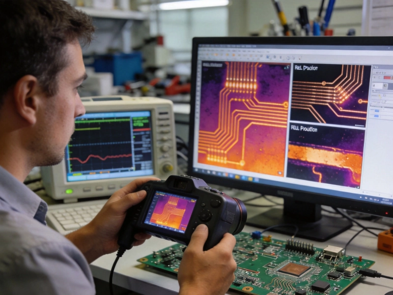
Thermal imaging under load reveals hot spots at bends, transitions, and areas where current crowds due to geometry changes. This testing should be performed with the flex section in its installed bend configuration, not flat, because bending changes the thermal environment.
Bend cycle testing with periodic resistance measurement detects developing fatigue before it causes open circuits. Track resistance on high-current paths, not just continuity—increasing resistance indicates developing cracks that will eventually fail.
Current cycling—repeatedly applying and removing rated current—tests the thermal expansion and contraction that flex assemblies experience in operation. This cycling stresses the rigid-flex transition and can reveal adhesive or copper fatigue that static testing misses.
Yes, but with significant limitations. Two-ounce copper in a flex section reduces bend cycle life substantially compared to 1-ounce copper. For static bend applications (bending once during assembly), 2-ounce copper is often acceptable. For dynamic bending applications, it's usually impractical—bend cycle life may drop to hundreds or low thousands of cycles.
Current capacity depends on trace width, copper weight, allowable temperature rise, and the thermal environment. A 1-ounce, 100-mil-wide flex trace might carry approximately 2 to 3 amps with 20°C rise in still air. Derating for bend effects and restricted cooling typically reduces practical capacity. Use IPC-2223 calculations as a starting point and apply conservative derating.
For static bends, IPC-2223 recommends approximately 6 times the total flex thickness for single-layer constructions. For dynamic bending, 10 to 12 times the thickness. High-current traces with heavier copper may require more conservative radii—perhaps 15 to 20 times thickness—to avoid resistive increases at the bend.
If possible, route high-current paths through rigid sections and use the flex section only for signals and low-current connections. When power must route through flex, apply the derating and design strategies discussed in this article. Sometimes the best solution is architectural—rethinking the board partitioning to keep power paths on rigid sections.
Monitor trace resistance during bend cycle testing. Increasing resistance indicates developing microcracks before they cause complete opens. Measure resistance to milliohm precision using a 4-wire (Kelvin) measurement technique. This gives early warning of fatigue that simple continuity testing cannot detect.
Contact us to discuss your requirements.
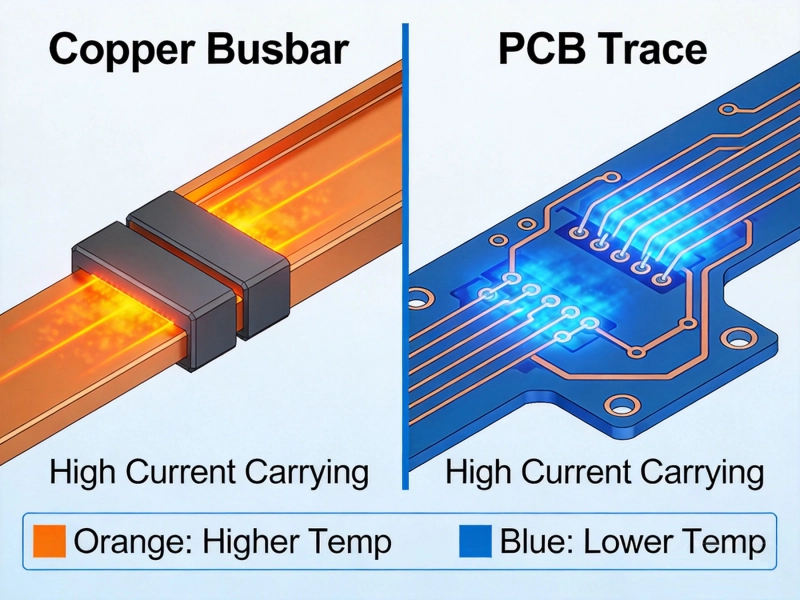
Bus Bar vs PCB Trace for High CurrentMay/21/2026
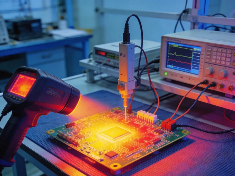
High Current PCB Testing: Thermal Imaging vs. 4-Wire Kelvin MeasurementJuly/22/2026
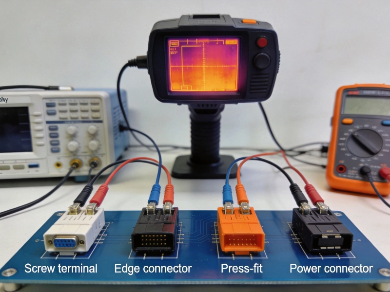
High Current PCB Connector Selection: Test Results and Real Performance DataMay/21/2026
IPC-2152 Current Carrying Capacity: The Definitive PCB Trace Calculator GuideMay/21/2026
High Current PCB Bus Bars vs. Heavy Copper Traces: Cost and PerformanceJuly/25/2026
High Current PCB Via Plating: 1mil vs. 2mil Thickness Reliability TestAugust/03/2026
High Current PCB Annular Rings: Minimum Size vs. Reinforced SizeAugust/12/2026
Copper Pour vs Trace: What 3 Years of PCB Failures Taught UsMay/21/2026