

Rigorous manufacturing and testing ensure their reliability and longevity under demanding electrical and thermal conditions.
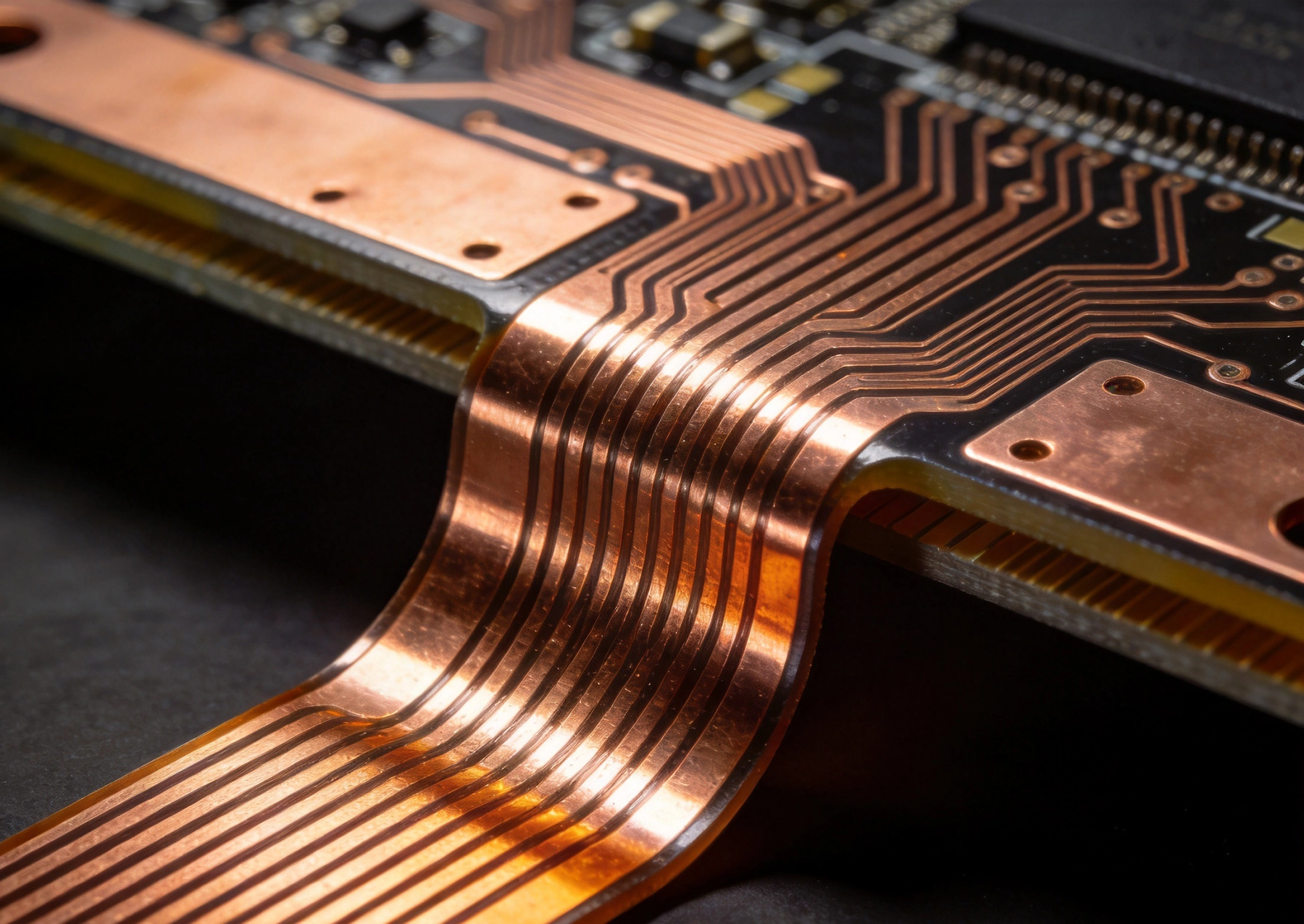
High Current PCB Flex-Rigid: Current Capacity in Bend AreasOctober/09/2026Rigid-flex PCBs solve real packaging problems. They eliminate connectors, reduce weight, and enable three-dimensional packaging that rigid boards alone can't achieve. But when you need to carry significant current—power for motors, battery systems, or high-wattage loads—through the flexible portio...
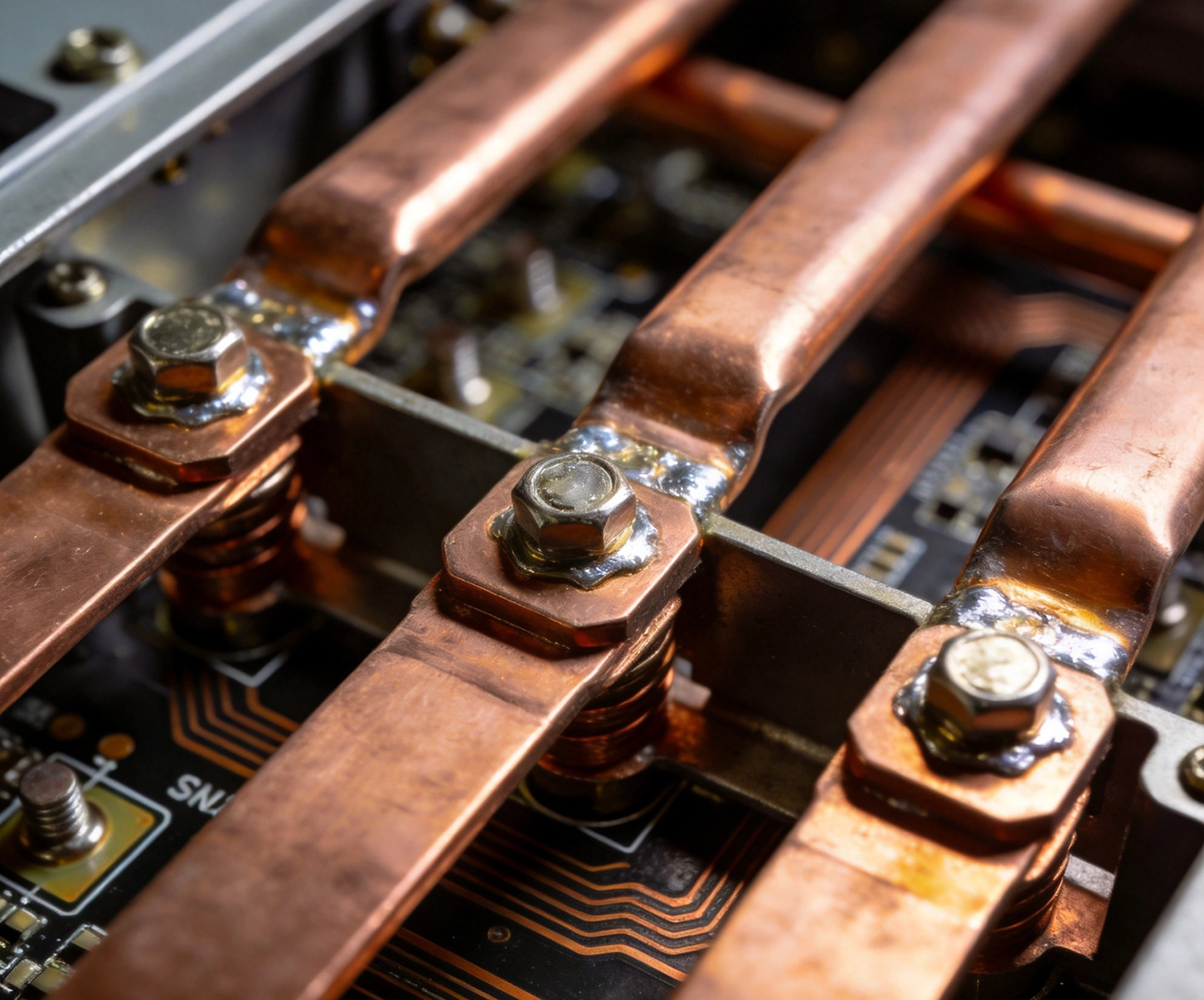
High Current PCB Design for Renewable Energy MicrogridsSeptember/30/2026Renewable energy microgrids are among the most demanding environments for power electronics. They must handle bidirectional power flow, operate reliably across wide temperature ranges, and do so while maintaining high conversion efficiency in systems that often run continuously for years without m...
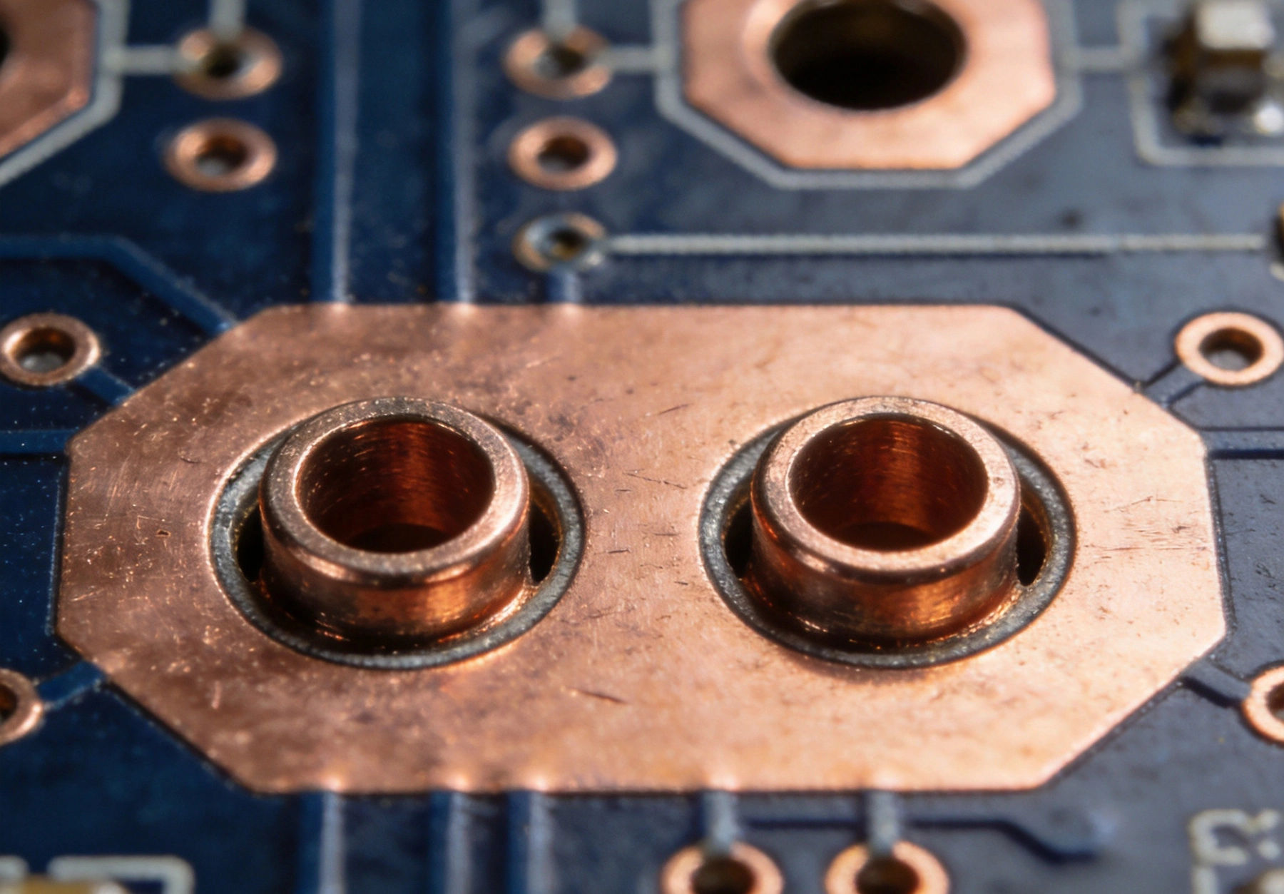
High Current PCB Mounting Holes: Plated vs. Non-Plated for Current ReturnSeptember/29/2026Mounting holes on printed circuit boards serve a dual purpose that many designers overlook: they secure the board to its chassis or enclosure, and when properly designed, they can also serve as critical current return paths between the PCB ground plane and the system chassis ground. For high-power...
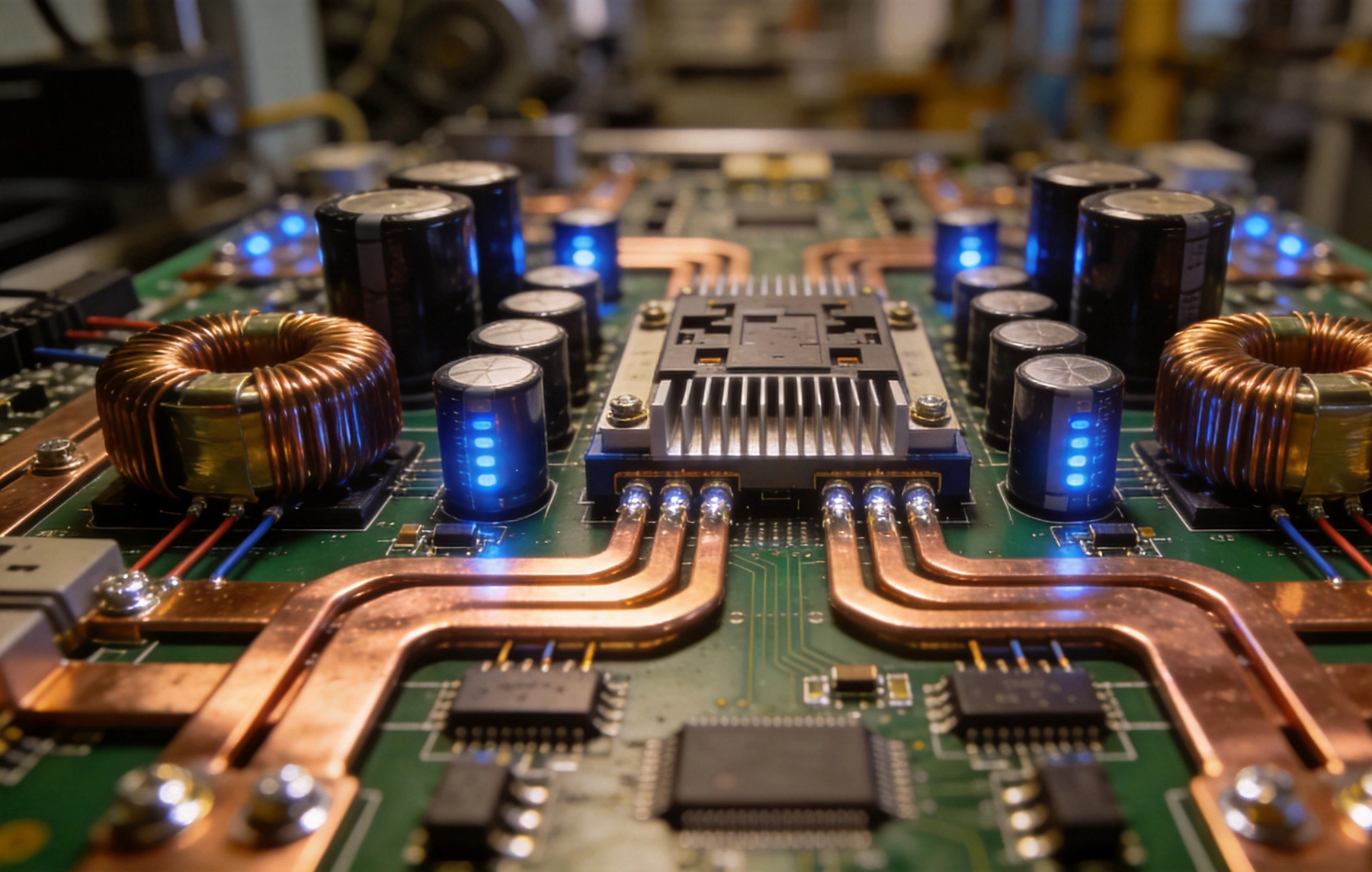
High Current PCB Design for Industrial Motor DrivesSeptember/28/2026Industrial motor drives are among the most demanding applications in power electronics. A variable frequency drive (VFD) controlling a 30kW motor might switch hundreds of amps at bus voltages of 400V to 690V, generating heat inIGBT modules, DC link capacitors, and the PCB traces that connect them....
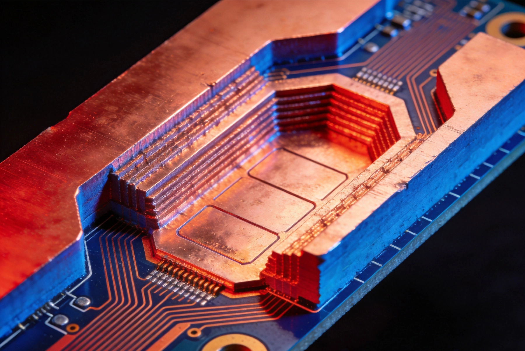
High Current PCB Embedded Copper: Internal vs. External Heat DissipationSeptember/26/2026In power electronics, managing heat is as important as managing current. A trace that can carry 20 amps on paper may fail in practice if the heat generated by I²R losses cannot escape the board fast enough. This is where the choice between internal embedded copper and external heavy copper becomes...
High Current PCB Design for High-Voltage DC TransmissionSeptember/24/2026High-voltage direct current (HVDC) transmission is experiencing a renaissance. As renewable energy sources—particularly offshore wind and remote solar farms—push power generation farther from population centers, HVDC's superior long-distance efficiency over AC transmission makes it the technology ...
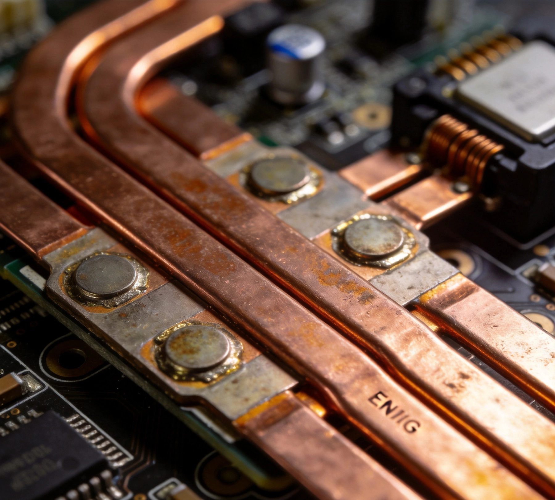
High Current PCB Surface Finish: ENIG vs. HASL for High Current PadsSeptember/23/2026High current PCB design presents unique challenges that standard surface finish selections may not address. When your board needs to carry tens or hundreds of amperes through power traces and pads, surface finish choice affects current carrying capacity, thermal performance, and long-term reliabil...
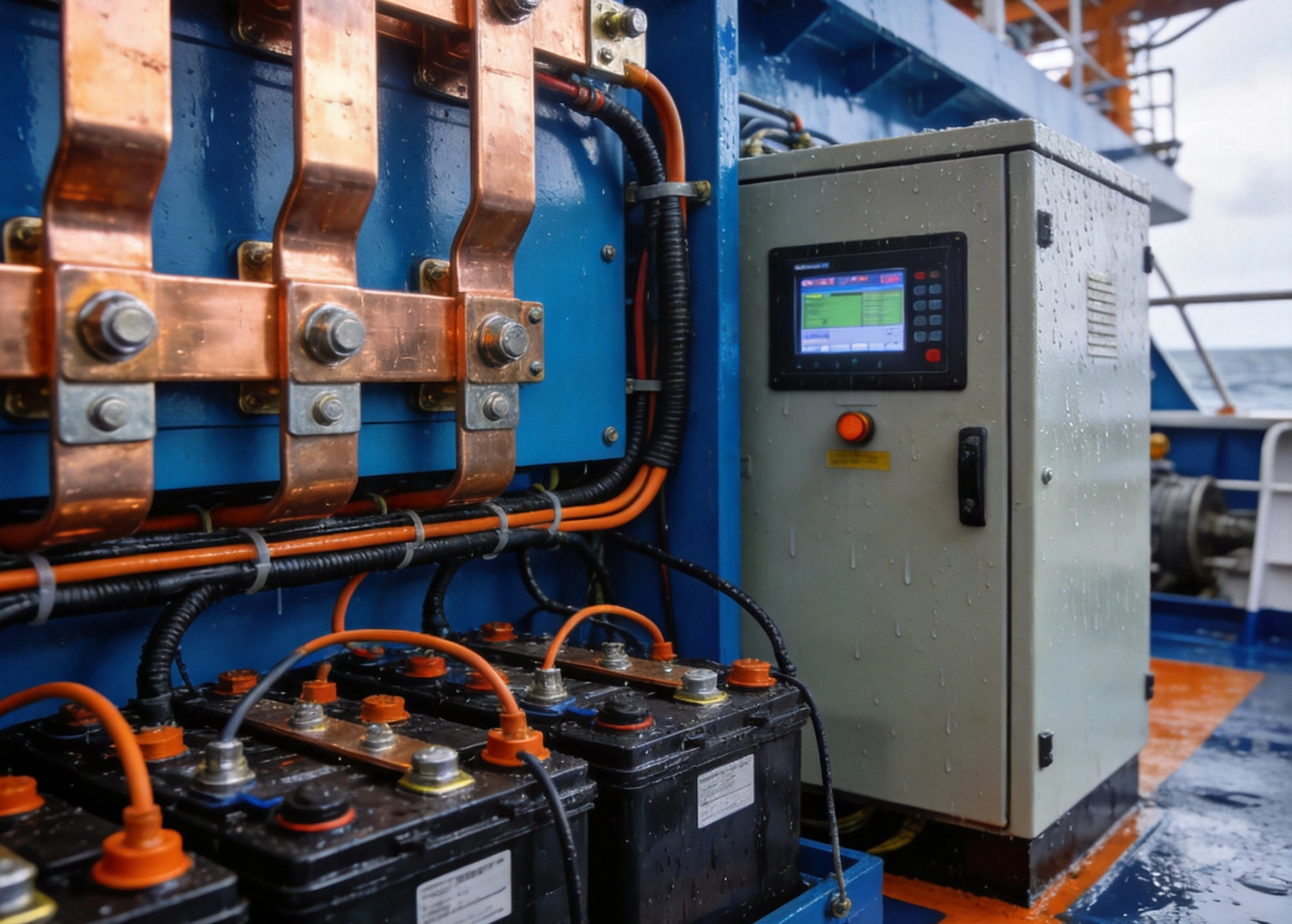
High Current PCB Design for Marine Battery SystemsSeptember/21/2026Marine battery systems operate in some of the most demanding environments in electronics. Whether powering electric ferries, offshore supply vessels, or recreational boats with advanced navigation systems, these battery banks must deliver high currents reliably while withstanding salt air, vibrati...
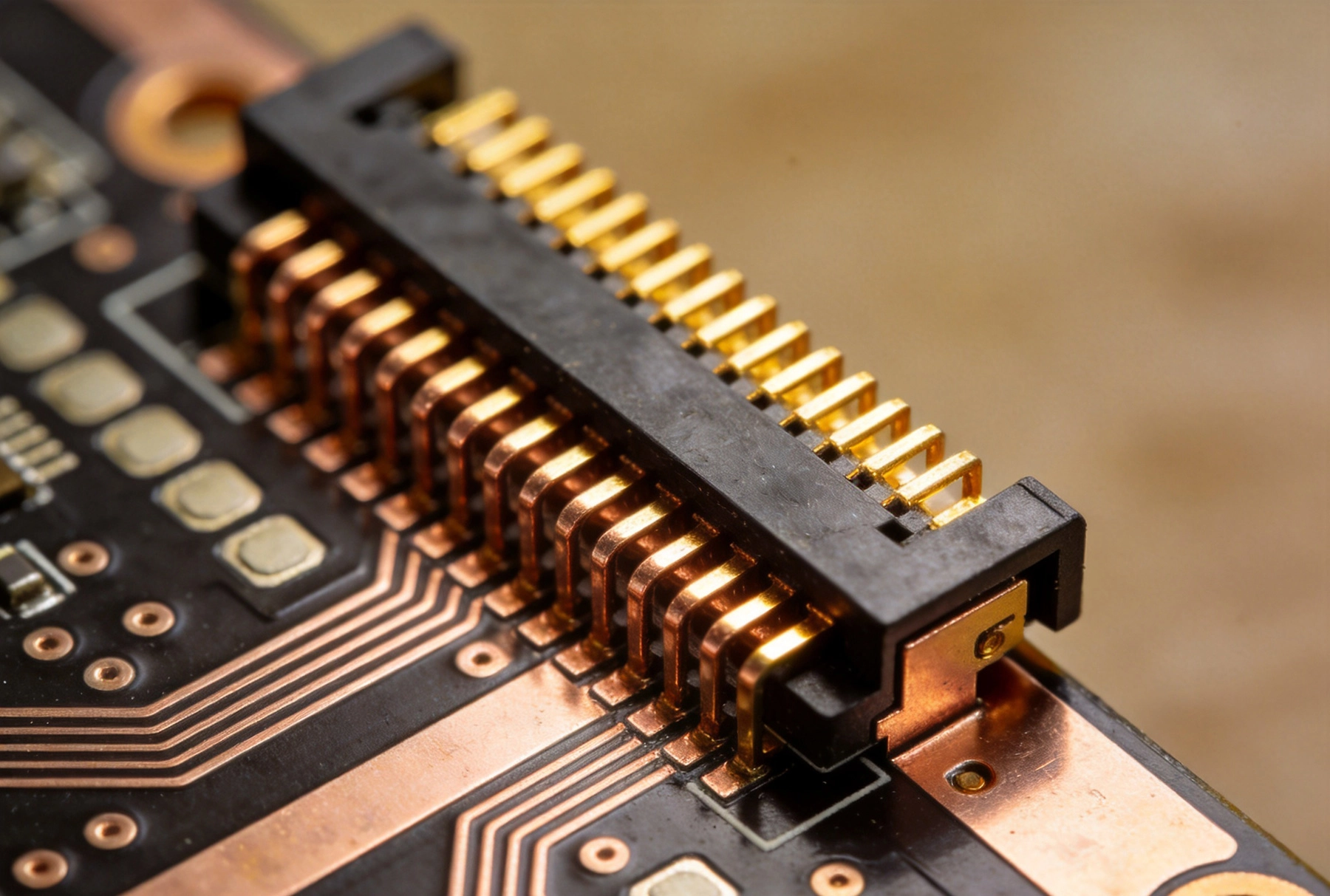
High Current PCB Edge Connectors: Current Rating and Thermal LimitsSeptember/20/2026Power delivery is the unsung backbone of every electronic system. While signal integrity and high-speed routing get the spotlight, the connectors that carry tens or hundreds of amperes into and out of a PCB determine whether a design runs cool and reliable or overheats and fails. High-current PCB ...
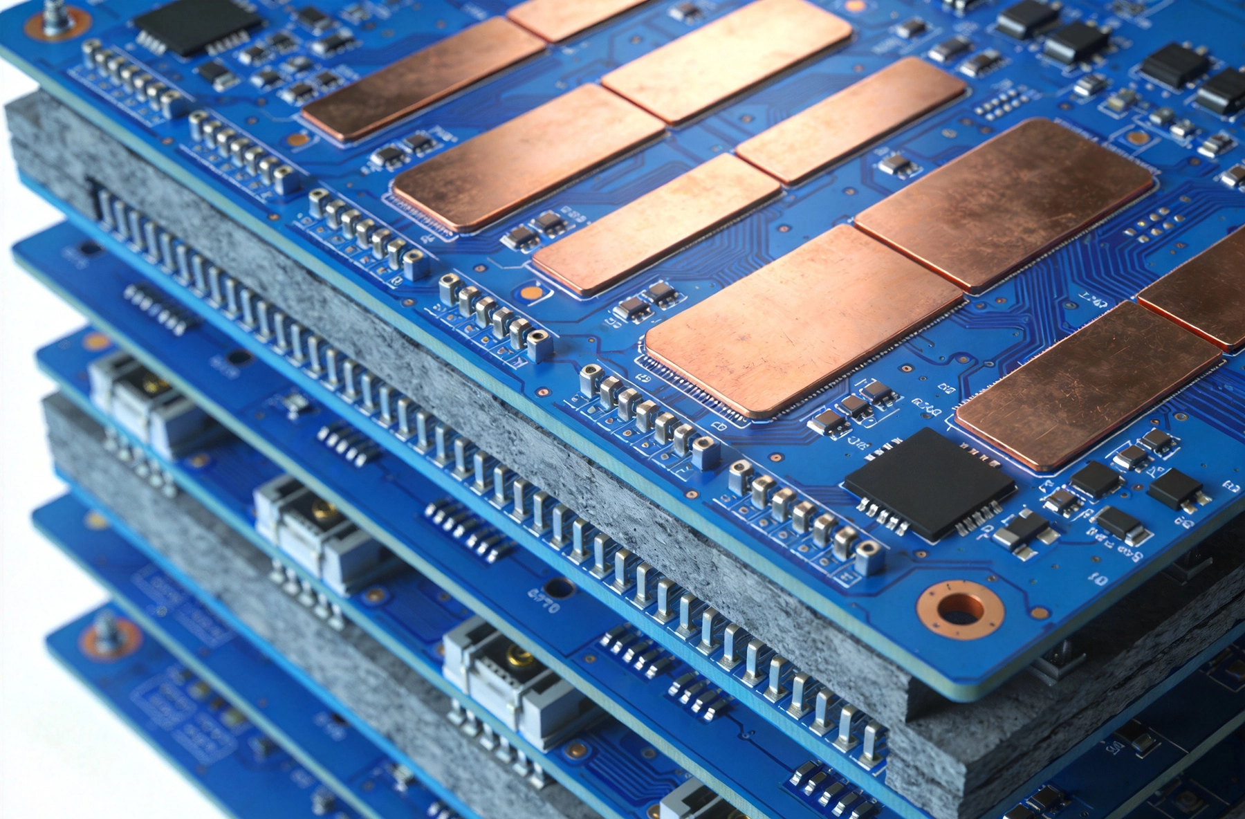
High Current PCB Design for Telecommunications Base StationsSeptember/18/2026Telecommunications base stations are among the most demanding environments for printed circuit board design. A single macro cell site houses power amplifiers, radio transceivers, filters, and baseband processing units — all running simultaneously, all generating heat, and all relying on a PCB infr...
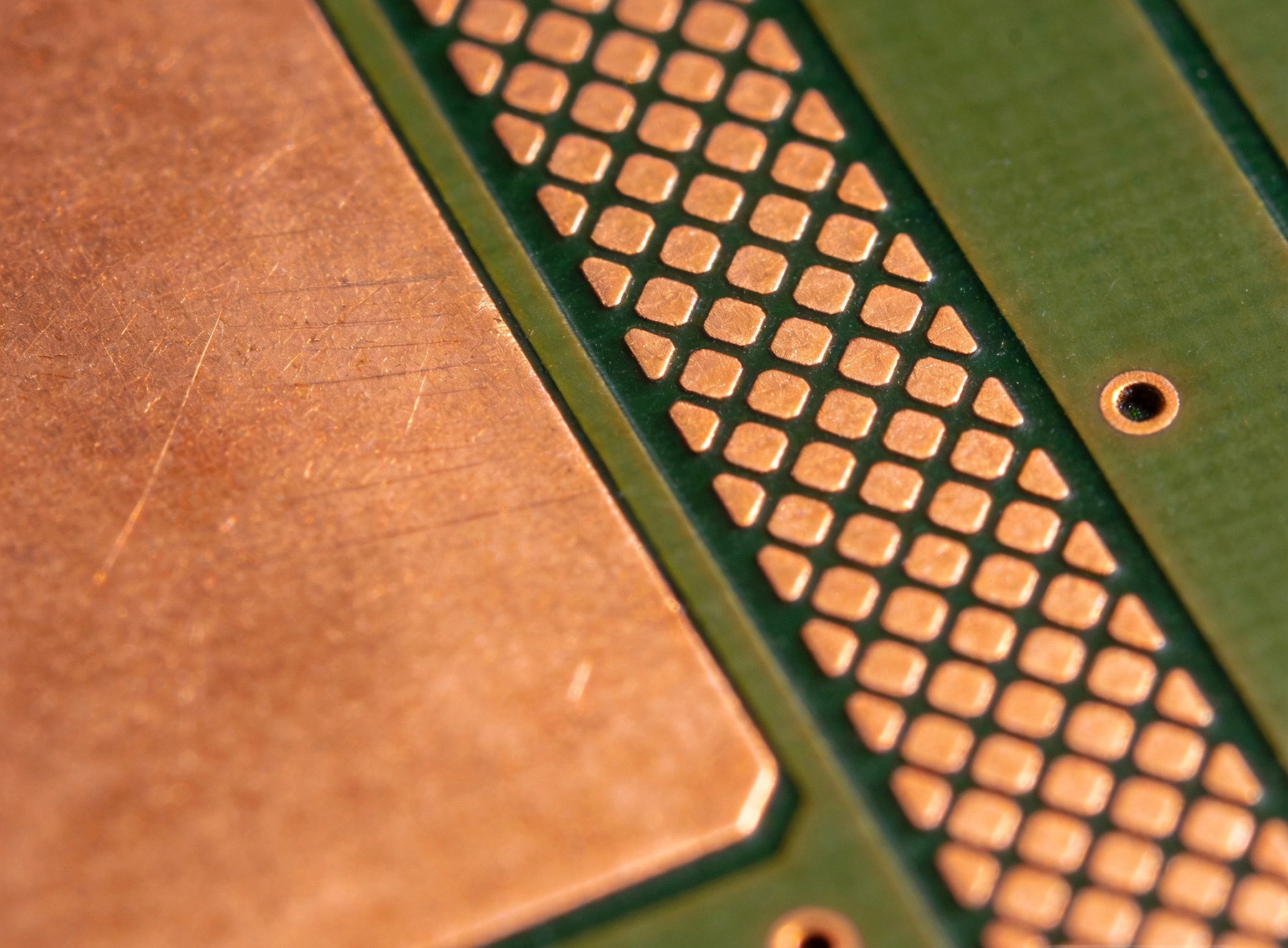
High Current PCB Copper Fill: Solid Pour vs. Hatched Pattern PerformanceSeptember/17/2026In power electronics PCB design, how you fill unused board area with copper matters more than most engineers realize. The choice between a solid copper pour and a hatched (crosshatch) copper pattern is not purely aesthetic—it directly impacts current carrying capacity, thermal dissipation, EMI shi...
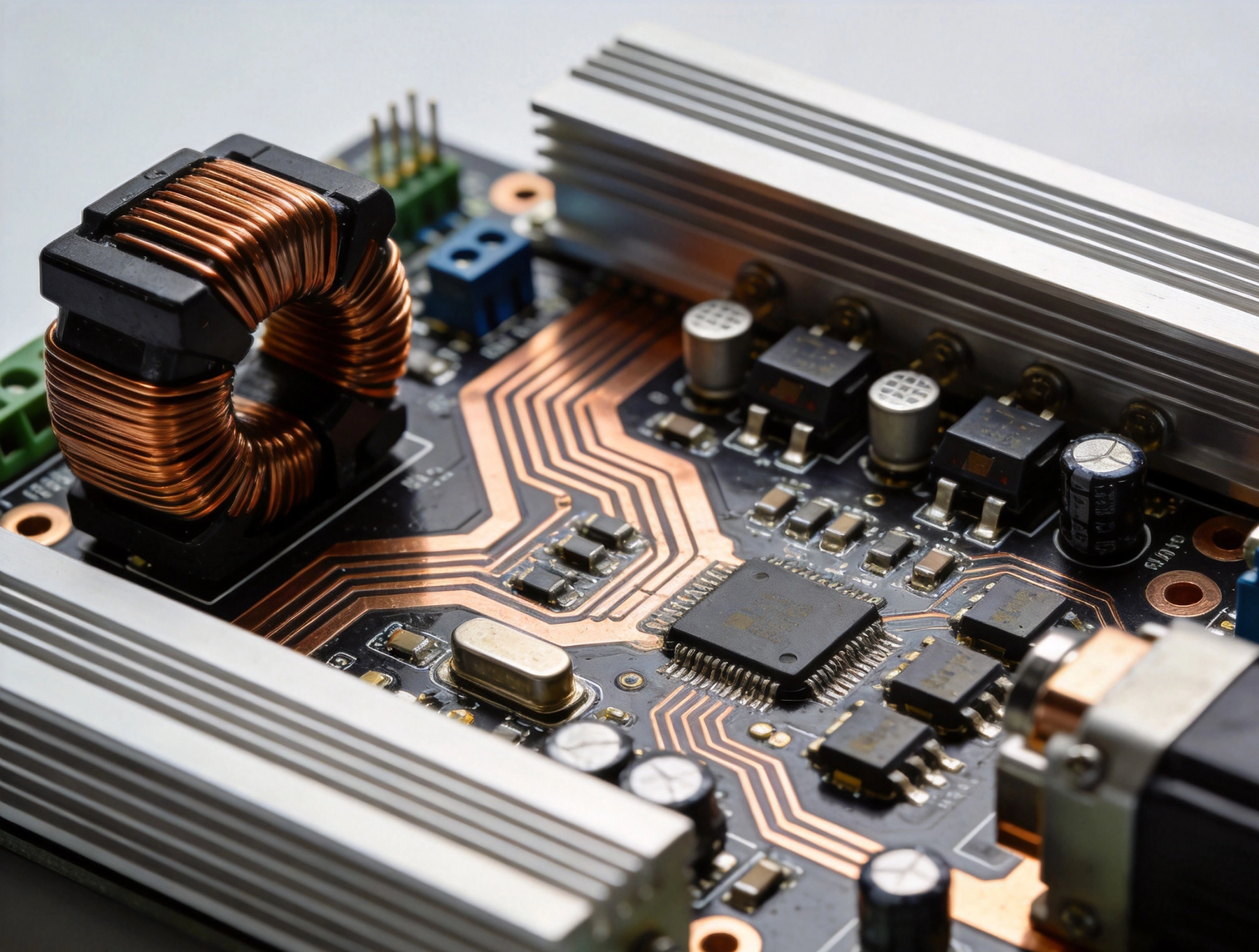
High Current PCB Design for Robotics Motor ControllersSeptember/16/2026Robotics motor controllers operate in one of the most demanding environments in power electronics. These systems must deliver high currents with precision timing, manage thermal loads from tens to hundreds of watts, and maintain reliability despite constant mechanical vibration and variable load c...
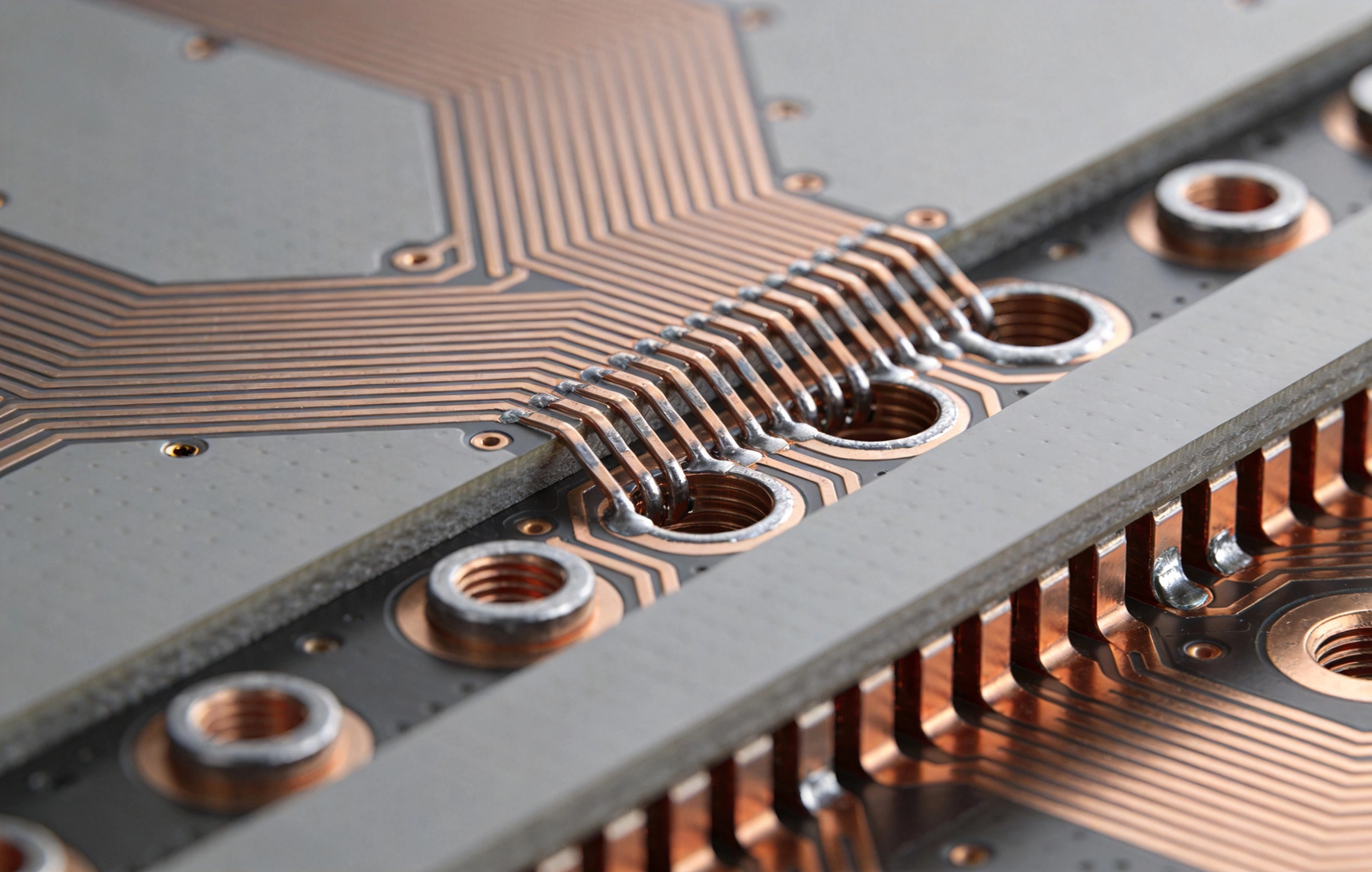
High Current PCB Thermal Vias: Array Spacing and Heat Transfer EfficiencySeptember/15/2026Heat has always been the enemy of electronics. In high current applications, this enemy grows stronger. Components that dissipate significant power generate thermal gradients across circuit boards, and if that heat isn't managed effectively, reliability suffers. The solution for many designers inv...
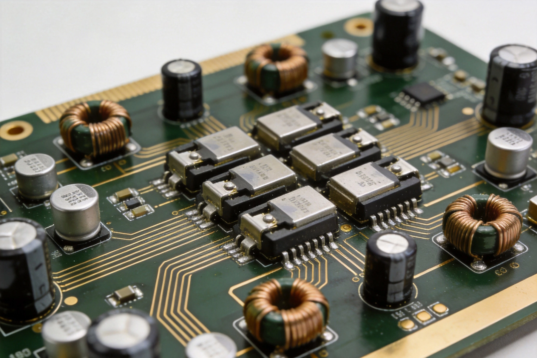
High Current PCB Design for Audio Amplifiers: Avoiding Ground LoopsSeptember/14/2026Designing a PCB for a high-current audio amplifier presents unique challenges that go beyond standard PCB layout practices. Audio amplifiers demand both precise low-level signal handling and robust power delivery, all while maintaining absolute silence—no humming, no buzzing, no RF interference. G...

High Current PCB Placed Slots vs. Standard Traces for Extreme CurrentsSeptember/11/2026When your PCB design needs to handle tens or hundreds of amps, ordinary copper traces quickly reach their limits. Standard PCB fabrication processes were designed for signals, not power. The copper weight, trace width, and thermal management techniques that work for low-current circuits simply do ...
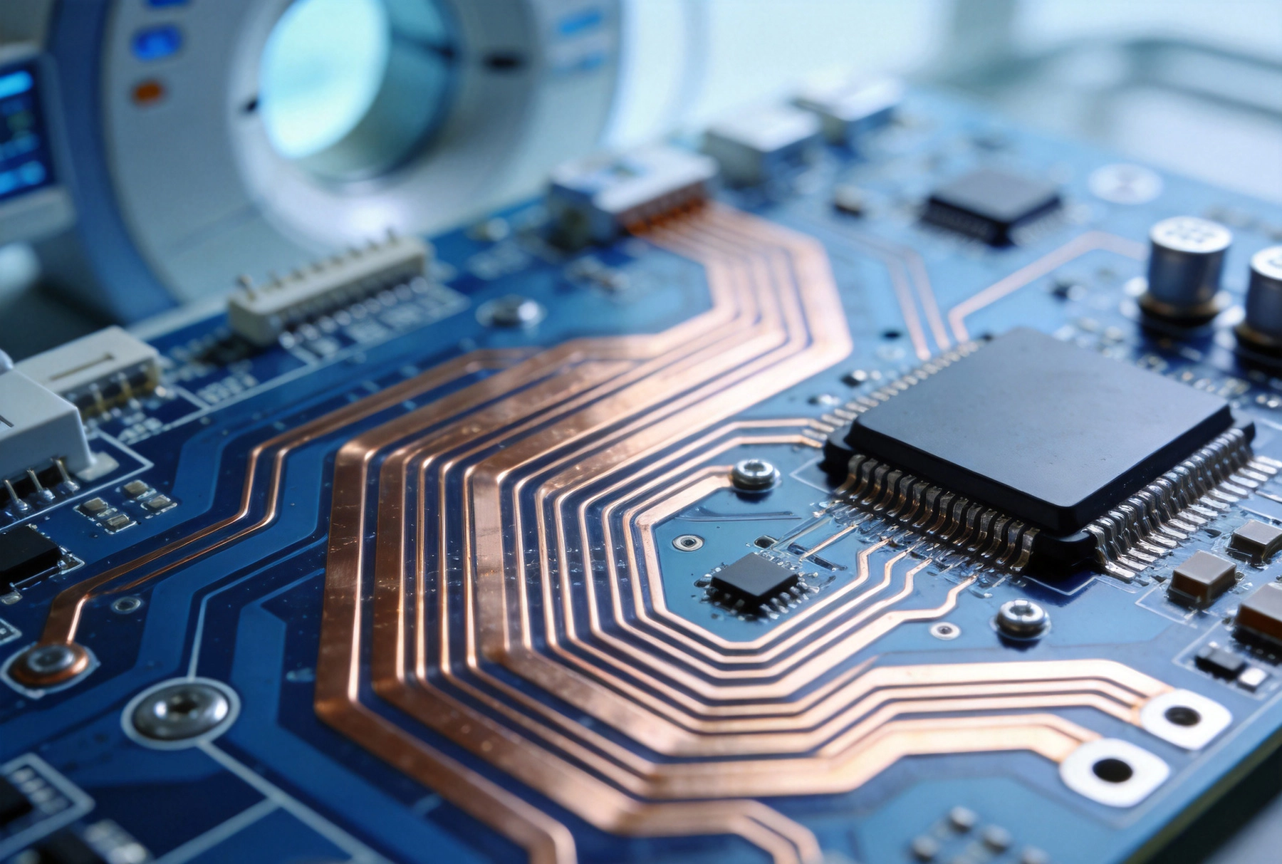
High Current PCB Design for Medical Imaging EquipmentSeptember/10/2026Medical imaging equipment represents one of the most demanding applications for high current printed circuit board (PCB) design, requiring exceptional reliability, precision, and safety in environments where component failure can have life-critical consequences. From magnetic resonance imaging (MR...
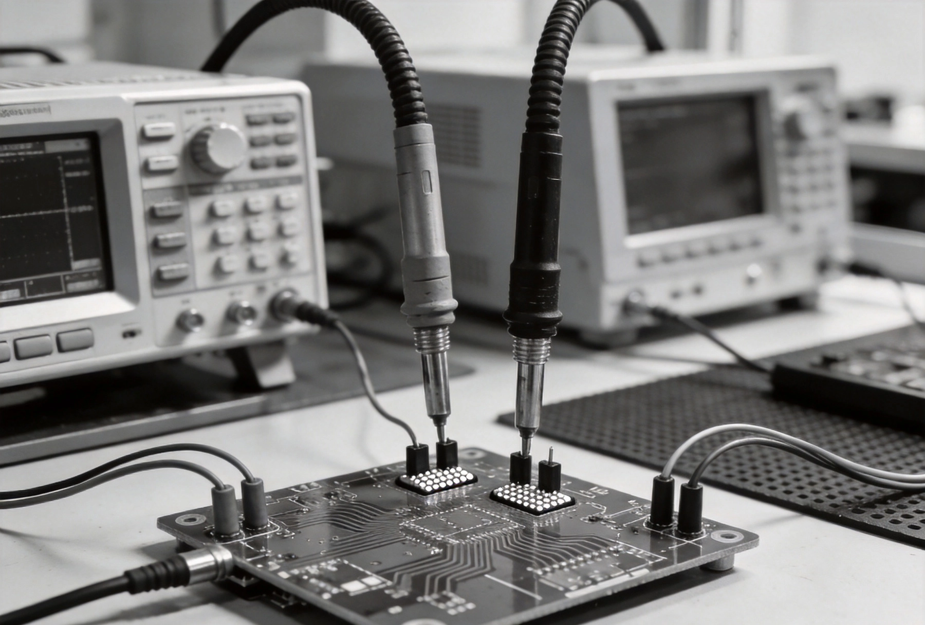
High Current PCB Kelvin Connections: Routing Best Practices for AccuracySeptember/09/2026Accurate current measurement stands as a cornerstone in power electronics design. Whether you are developing battery management systems, motor drives, or power supplies, the ability to measure current precisely determines system efficiency, safety, and performance. Kelvin connections, also known a...
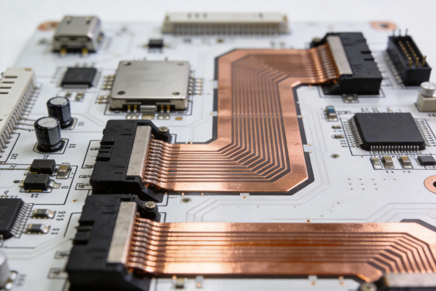
High Current PCB Design for Aerospace Power DistributionSeptember/08/2026Aerospace power distribution systems place demands on PCB design that are fundamentally different from those of commercial electronics. A single board in an aircraft or spacecraft may need to carry hundreds of amps across bus bars, distribute power to avionics modules, motor controllers, lighting ...
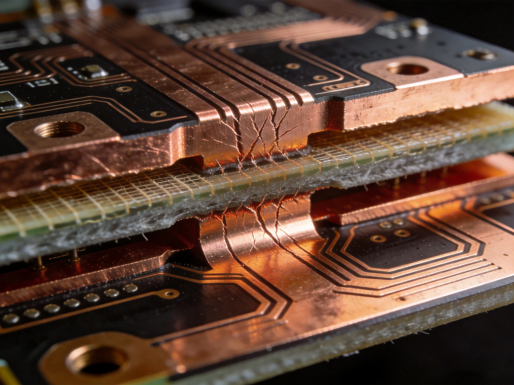
High Current PCB Copper Balancing: Preventing Warpage in Heavy Copper BoardsSeptember/07/2026Heavy copper PCBs power everything from electric vehicle chargers to industrial motor drives, carrying currents that would destroy standard circuit boards. Yet the very copper that makes these boards capable of handling high amperage also creates one of the most persistent manufacturing challenges...
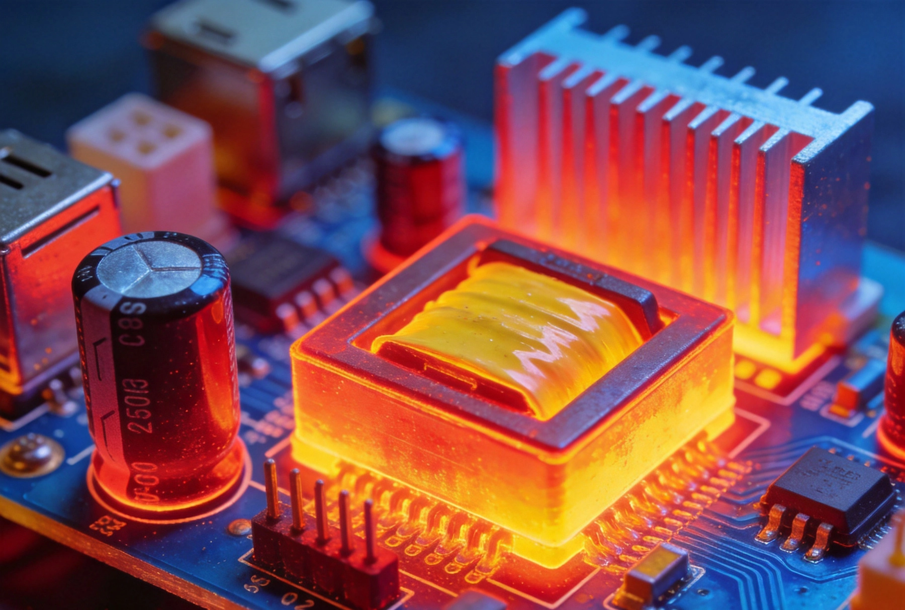
High Current PCB Design for High-Frequency Switching RegulatorsSeptember/04/2026High-frequency switching regulators power everything from server motherboards to automotive electronics. At frequencies above 500 kHz—and increasingly pushing past 1 MHz—these power conversion circuits demand PCB layouts that would make an aerospace engineer nervous. The difference between a relia...
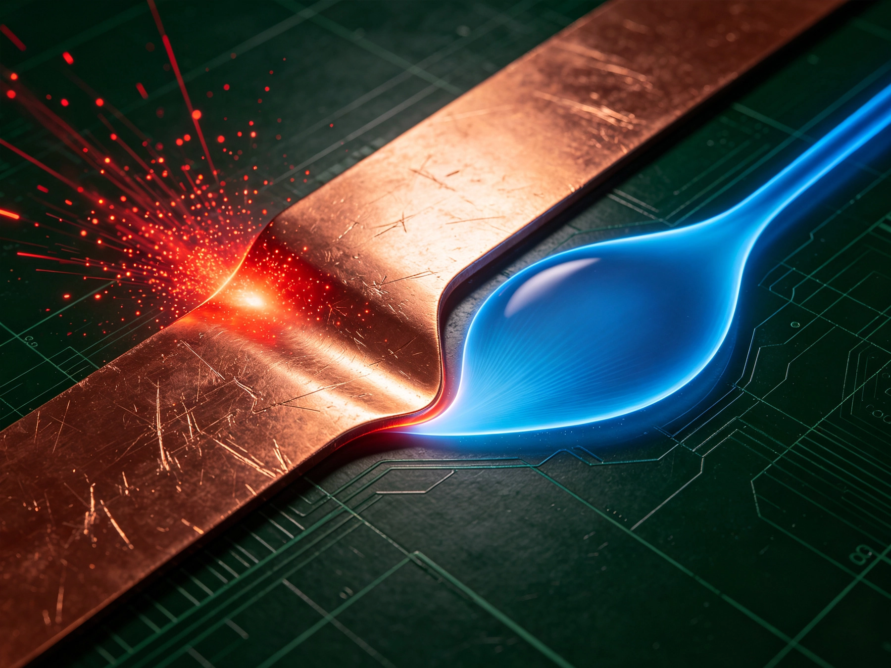
High Current PCB Current Crowding: Sharp Corners vs. Teardrop TransitionsSeptember/03/2026High current printed circuit board design presents unique challenges that go far beyond simple width calculations based on current requirements. One of the most critical yet often overlooked aspects involves current crowding effects at trace transitions, particularly where conductors make sharp tu...
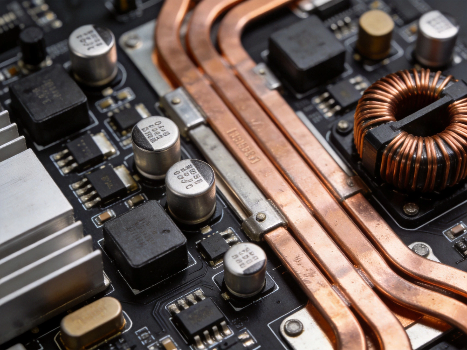
High Current PCB Design for Uninterruptible Power Supplies (UPS)September/02/2026Uninterruptible Power Supplies (UPS) are critical for protecting sensitive electronic equipment from power outages, voltage fluctuations, and surges. From small desktop units protecting home computers to industrial-scale UPS systems protecting data centers, hospitals, and manufacturing facilities,...
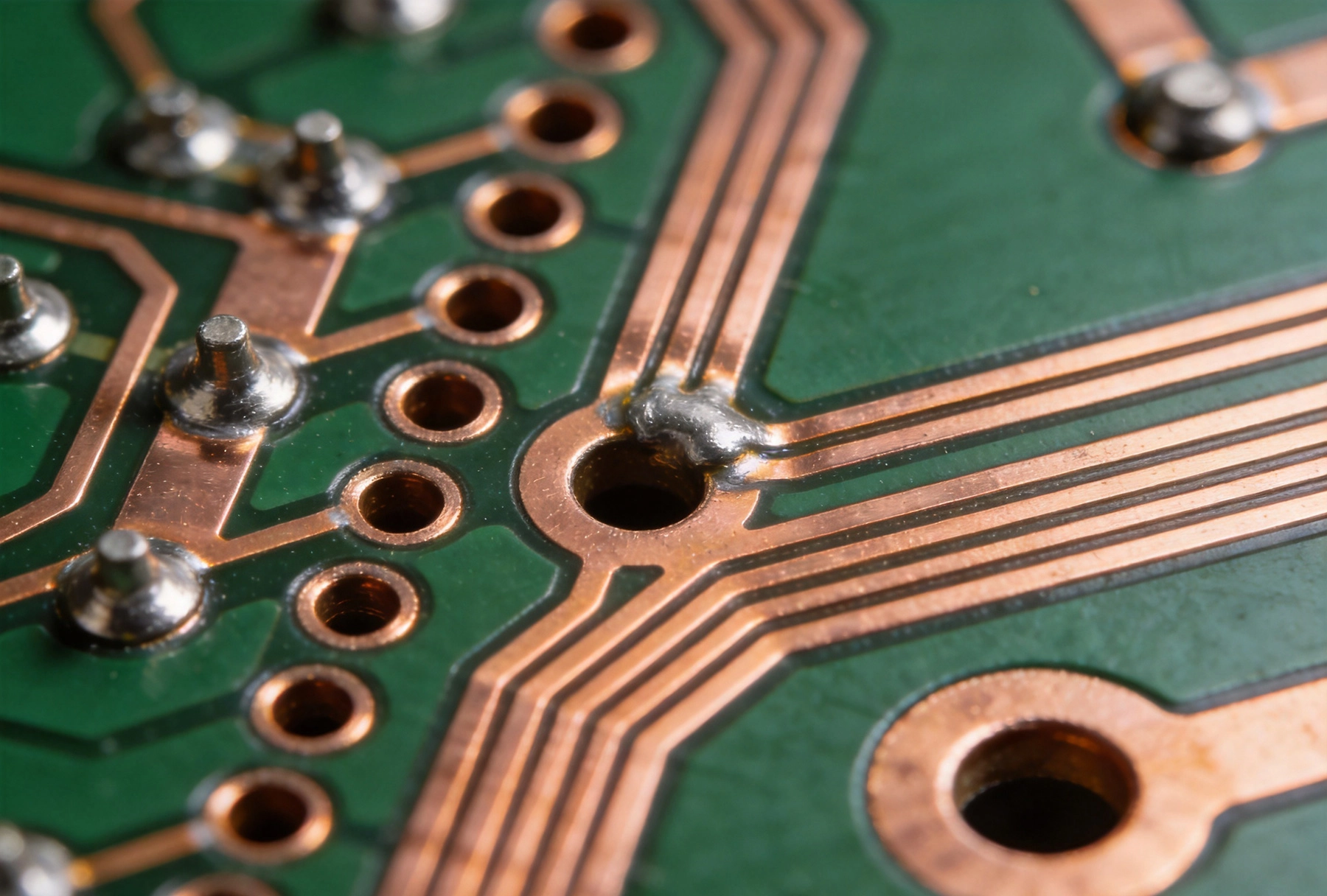
High Current PCB Solder Wicking: Tented Vias vs. Untented ViasSeptember/01/2026High current PCB design presents unique challenges, with solder wicking into vias being a critical concern during assembly. When solder melts and flows away from component pads into via holes, it creates insufficient solder joints that compromise electrical and mechanical reliability. This article...
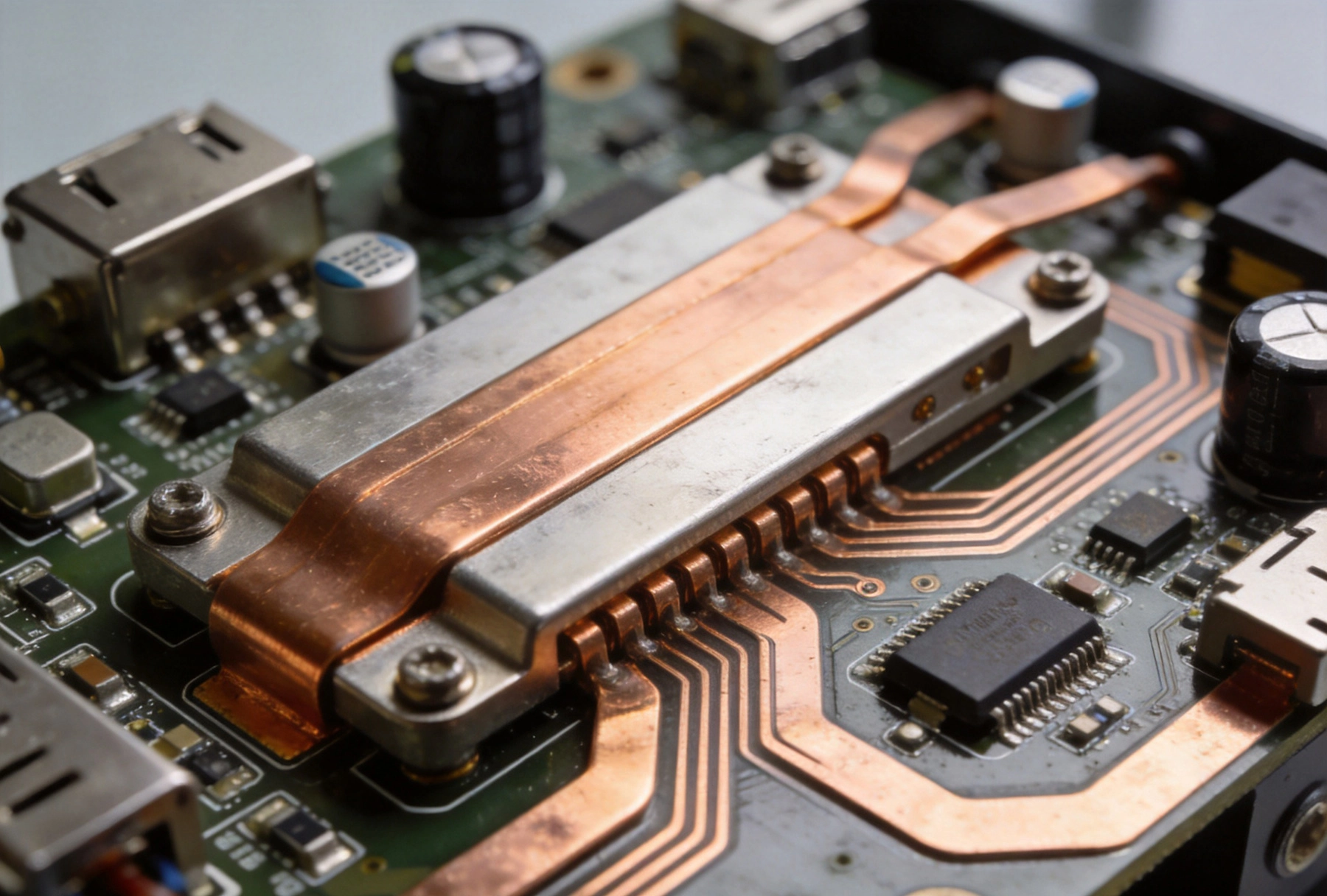
High Current PCB Design for Electric Vehicle Charging StationsAugust/15/2026The rapid growth of electric vehicle adoption has created unprecedented demand for reliable, high-power charging infrastructure. At the heart of every EV charging station lies a sophisticated power electronics system, with printed circuit boards serving as the critical foundation for power convers...