
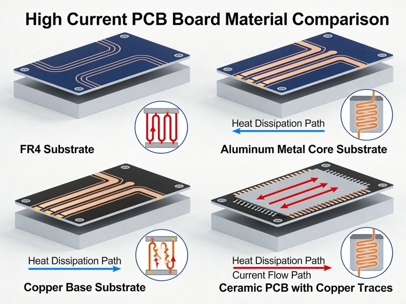
A practical selection guide based on current capacity, thermal needs, and budget constraints
I once spent three weeks redesigning a 100A motor controller because I chose the wrong PCB material. Standard FR-4 couldn't handle the thermal load, and the board delaminated after 50 hours of testing. That mistake cost $15,000 in prototypes and delayed the project by a month. Here's what I learned: picking the best material for High Current Pcb Design isn't about finding the "best" material—it's about finding the right material for your specific current, thermal, and cost constraints.
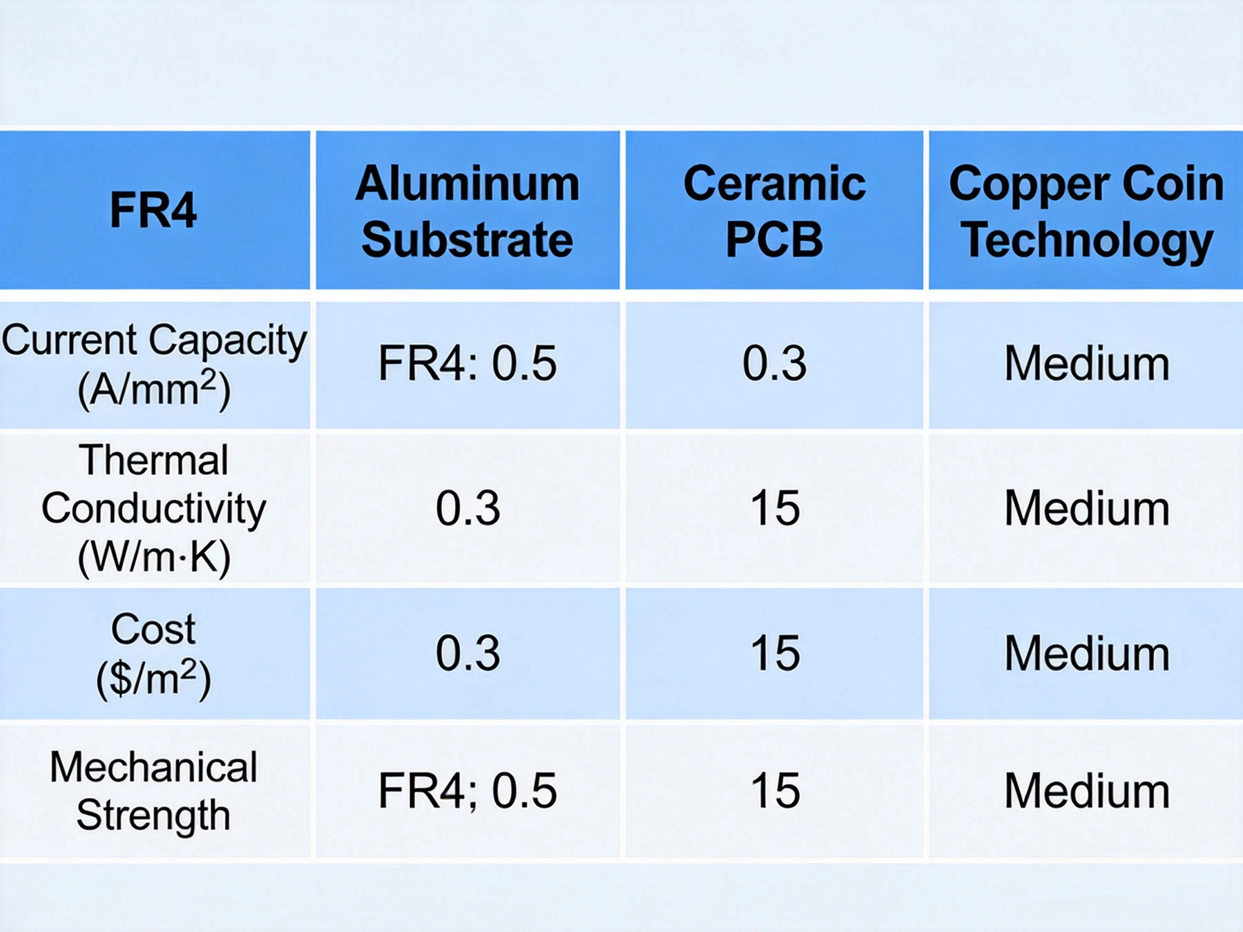
| Material | Max Current | Thermal Conductivity | Cost | Best For |
|---|---|---|---|---|
| Standard FR-4 | Up to 20A | 0.3 W/mK | $ | Low-power, cost-sensitive |
| High-Tg FR-4 | Up to 30A | 0.4 W/mK | $$ | Extended temperature range |
| Aluminum Pcb (MCPCB) | Up to 50A | 1-3 W/mK | $$$ | LED, power converters |
| Copper-Invar-Copper | Up to 100A | 15-20 W/mK | $$$$ | Military, aerospace |
| Ceramic (Al₂O₃) | Up to 200A | 20-30 W/mK | $$$$ | RF power, high-frequency |
| Ceramic (AlN) | Up to 500A | 170 W/mK | $$$$$ | Extreme thermal applications |
The default choice for most PCBs, but with significant limitations for High Current.
When to use: Consumer electronics under 15A, cost-sensitive designs, prototypes
An upgraded version of standard FR-4 with better thermal stability.
When to use: Industrial equipment, automotive, applications to 85°C ambient
The sweet spot for many High Current applications, offering excellent thermal performance at reasonable cost.
When to use: LED lighting, power supplies to 500W, motor drives, automotive lighting
Aluminum PCB offers the best balance of thermal performance, cost, and manufacturability for most high current designs. If your current is between 20-50A, start here.
A specialized material combining copper's conductivity with Invar's dimensional stability.
When to use: Military/aerospace, power modules, applications with ceramic components
The ultimate solution for extreme thermal and electrical performance.
When to use: RF power amplifiers, IGBT modules, EV traction inverters, high-power laser drivers
Unless you're building 100kW+ systems or operating at GHz frequencies, ceramic is probably overkill. Consider copper coin technology on FR-4 as a cost-effective alternative.
Follow this logic to find your best material:
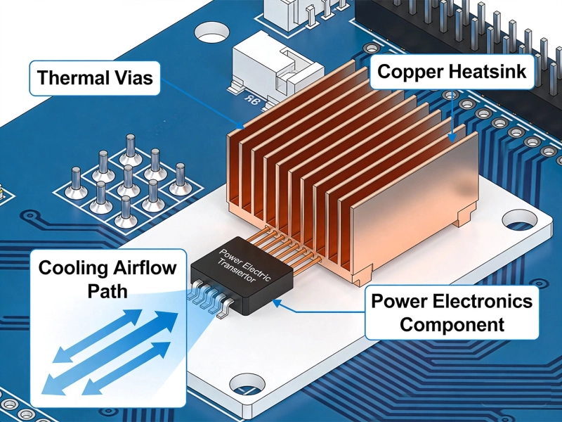
Embed thick copper slugs (coins) in standard FR-4 boards:
Use 3-10 oz copper instead of standard 1 oz:
Aluminum core with multilayer construction:
Choice: Aluminum PCB (MCPCB)
Why: LED junction temperature critical, 10A manageable with MCPCB thermal conductivity, cost-effective for production volumes
Result: LED baseplate temperature reduced from 85°C to 55°C vs FR-4
Choice: Ceramic (AlN) substrate for power module
Why: Extreme current requires maximum thermal conductivity, reliability critical, space limited
Result: IGBT junction temperature maintained below 125°C at full load
Choice: High-Tg FR-4 with 3 oz copper
Why: Cost constraints, moderate current, existing supplier relationships
Result: 40% cost savings vs MCPCB, acceptable thermal performance with forced air
| Material | Relative Cost | Relative Thermal Performance | Value Score |
|---|---|---|---|
| Standard FR-4 | 1× | 1× | ★★★★★ |
| High-Tg FR-4 | 1.5× | 1.3× | ★★★★☆ |
| Aluminum PCB | 3× | 8× | ★★★★★ |
| Copper Coin FR-4 | 2.5× | 5× | ★★★★☆ |
| CIC | 10× | 60× | ★★★☆☆ |
| Ceramic (Al₂O₃) | 20× | 80× | ★★★☆☆ |
| Ceramic (AlN) | 50× | 500× | ★★☆☆☆ |
Start with High-Tg FR-4 and heavy copper (2-3 oz). It's familiar to most PCB shops, prototyping is fast, and you won't outgrow it until 30A+. Upgrade to aluminum PCB only when thermal testing proves necessary.
Invest in Aluminum PCB (MCPCB) for currents above 15A. The material cost premium pays for itself through:
Budget for Ceramic or CIC from day one. The cost of failure far exceeds the material premium. Build relationships with specialized manufacturers early—lead times can be 8-12 weeks.
There's no universal "best" material for High Current Pcb Design—only the best material for your specific application. Start with your current requirements, factor in thermal constraints and budget, then select accordingly.
Most engineers over-specify materials, paying for ceramic when aluminum would suffice. Don't fall into that trap. Prototype with conservative choices, measure real thermal performance, and upgrade only when data proves it's necessary.
Remember: the material is just one part of the thermal puzzle. Trace width, via design, and component placement matter just as much. Optimize the whole system, not just the substrate.
Best Material for High Current PCB Design: How to Choose the Right SubstrateJune/05/2026
How Much Current Can a PCB Trace Carry? Complete Engineering GuideMay/20/2026
Why Your High-Power PCBs Overheat (And the 5 Methods That Actually Fix It)May/20/2026
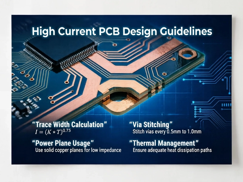
High Current PCB Design Guidelines: Ensuring Reliability and SafetyJune/08/2026
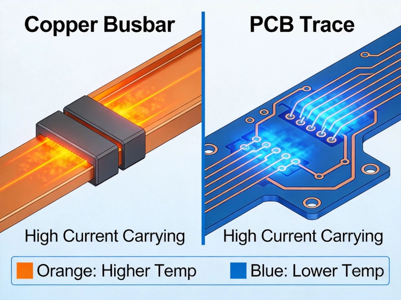
Bus Bar vs PCB Trace for High CurrentMay/21/2026
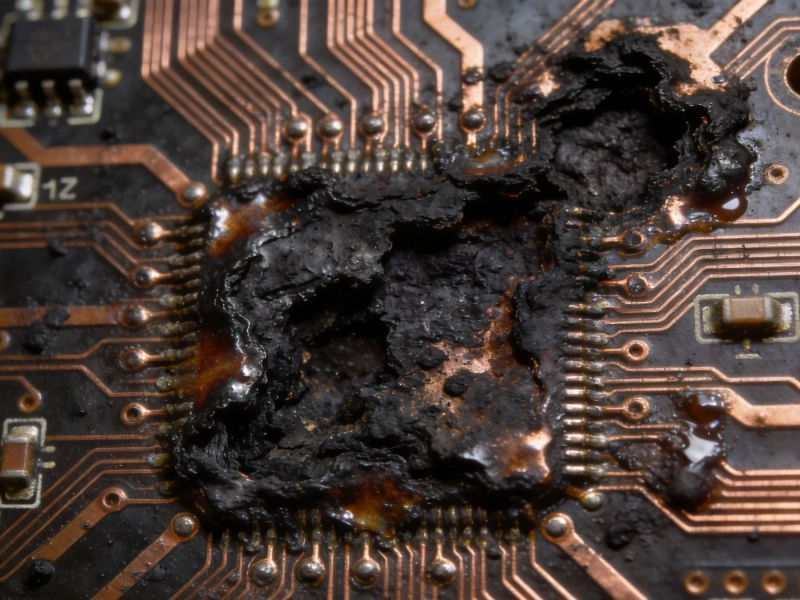
High Current PCB Failure Modes and PreventionJune/18/2026
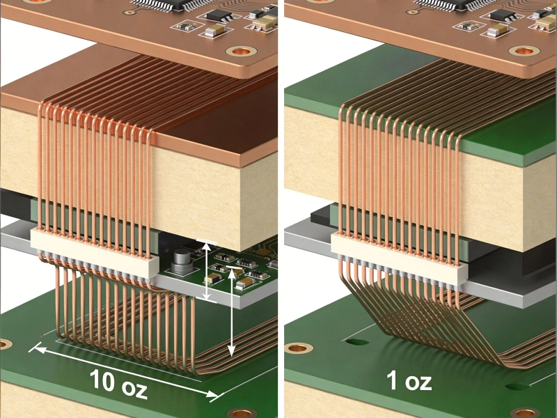
Heavy Copper vs Standard Copper PCB: Complete Comparison Guide for EngineersMay/20/2026
How to Reduce Temperature Rise in Power PCBJune/17/2026