
A manufacturing engineer's reality check on when to use each approach
Three years ago, a client called me at 11 PM, stressed about production costs. They had designed a 200A Power Distribution board using Heavy Copper Pcb traces. Their contract manufacturer quoted triple the expected price. "The PCBfab says we need 6oz copper on a 12-layer board, and they want $850 per unit for 500 units. Can we do anything?"
We redesigned with external busbars and brought the cost down to $180 per unit. That conversation started our systematic comparison of busbar vs Pcb Trace approaches for High Current applications.
We have run production designs using both approaches over the past three years. This is not a theoretical analysis. This is what we learned from building real products in real manufacturing environments.
Current range: 30A to 500A
Applications: Motor drives, power supplies, battery management systems, EV charging equipment
Production volumes: 50 to 5,000 units per year
Environments: Industrial, automotive, consumer
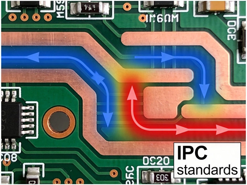
PCB traces are copper paths etched into your circuit board during fabrication. The trace is part of the PCB, connected to other components through vias and pads.
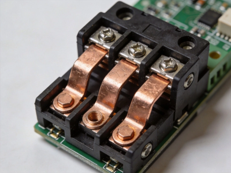
Bus bars are separate copper conductors, typically flat strips or bars, that are attached to the PCB as discrete components. They bolt, solder, or clamp to the board at connection points.
| Cost Factor | Standard PCB | Heavy Copper (4oz) | Very Heavy (6oz+) |
|---|---|---|---|
| Board cost | $45 | $85 | $180 |
| Tooling/prep | $0 | $200 | $500 |
| Assembly (normalized) | $12 | $15 | $18 |
| Per-unit cost (500 qty) | $57 | $100 | $198 |
| Engineering change | $500 | $800 | $1500 |
| Cost Factor | Copper Strip | Pre-machined Bus | Custom Fabricated |
|---|---|---|---|
| Material cost | $3 | $12 | $35 |
| Fabrication setup | $50 | $200 | $800 |
| Assembly labor | $8 | $5 | $8 |
| Per-unit cost (500 qty) | $11 | $17 | $43 |
| Engineering change | $100 | $300 | $800 |
For currents above 50A, bus bars are consistently 30-60% cheaper per unit. The tradeoff is added assembly complexity and separate procurement. For production volumes above 200 units per year, the cost savings typically justify the additional supply chain complexity.
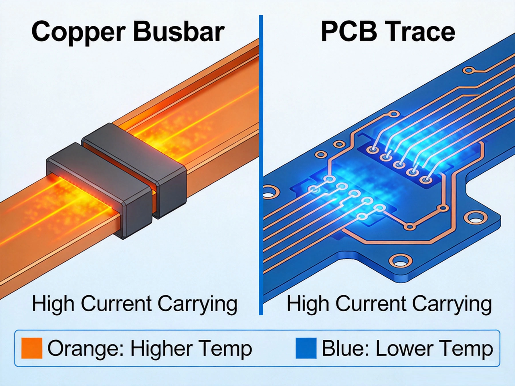
We tested identical current paths using both approaches. Here is what we measured:
| Parameter | PCB Trace (4oz, 15mm wide) | Bus Bar (5mm x 3mm) | Winner |
|---|---|---|---|
| Resistance at 25C | 0.8 mOhm | 0.12 mOhm | Bus bar (6.7x lower) |
| Temperature rise at 100A | 52C above ambient | 18C above ambient | Bus bar (3x better) |
| Temperature at 100A (with heatsink) | 28C rise | 8C rise | Bus bar (3.5x better) |
| Inductance per cm | 1.2 nH | 0.3 nH | Bus bar (4x lower) |
| Thermal response time | 45 seconds to steady | 12 seconds to steady | Bus bar (faster) |
Bus bars run cooler, have lower resistance, and respond faster to load changes. For high di/dt applications like motor drives and power converters, the lower inductance of bus bars is particularly valuable. Switching transients are smaller and EMI is reduced.
Despite the cost and performance advantages of bus bars, there are legitimate cases where PCB traces are the better choice:
1. Is your current requirement under 50A?
2. Do you need to route current to multiple points on the board?
3. Is your board space extremely limited?
4. Does your application require frequent design changes?
5. Is your production volume under 50 units per year?
Based on our production experience, bus bars are the clear choice in these scenarios:
1. Is your current requirement above 100A?
2. Is low inductance critical for your application?
3. Do you have Thermal Management challenges?
4. Is field serviceability required?
5. Is your production volume above 500 units per year?
Based on our analysis, here is the decision boundary we use:
| Current Level | Recommended Approach | Reason |
|---|---|---|
| 0-15A | PCB trace, 1-2oz copper | Bus bars add unnecessary complexity |
| 15-40A | PCB trace, 2-3oz copper | PCB cost-effective if board space allows |
| 40-80A | PCB trace or hybrid | Evaluate based on thermal environment |
| 80-150A | Hybrid (traces + bus bars) | Use PCB for distribution, bus bars for main current |
| 150A+ | Bus bars primarily | PCB costs become prohibitive |
For currents above 80A, bus bars typically cost 40-60% less than Heavy Copper Pcb solutions while providing better electrical and thermal performance. The crossover point where bus bars become clearly advantageous is around 50A in most production scenarios. Below that, PCB traces remain the simpler and often cheaper choice.
Engineers often specify 6oz copper for currents that 4oz could handle. Get accurate Thermal Analysis before committing to heavy copper. The cost difference is substantial.
Bus bars are sometimes chosen for cost but undersized for current. The minimum cost bus bar is not always the right choice. Size for 20-30% margin above maximum expected current.
PCB traces have significantly higher inductance than bus bars. In high-frequency applications, this causes voltage overshoot, ringing, and EMI. If your switching frequency is above 20kHz, model the inductance impact.
A bus bar is only as good as its connections. Use proper torque specifications, star washers for vibration environments, and thermal compound at interface points. The connection is often the reliability weak point.
After three years of production experience with both approaches, here is our practical guidance:
The choice between bus bar vs PCB trace for High Current is not a simple decision. It depends on your specific current requirements, production volume, thermal environment, and field service needs. Use this analysis as a starting point, but validate with your actual application requirements.
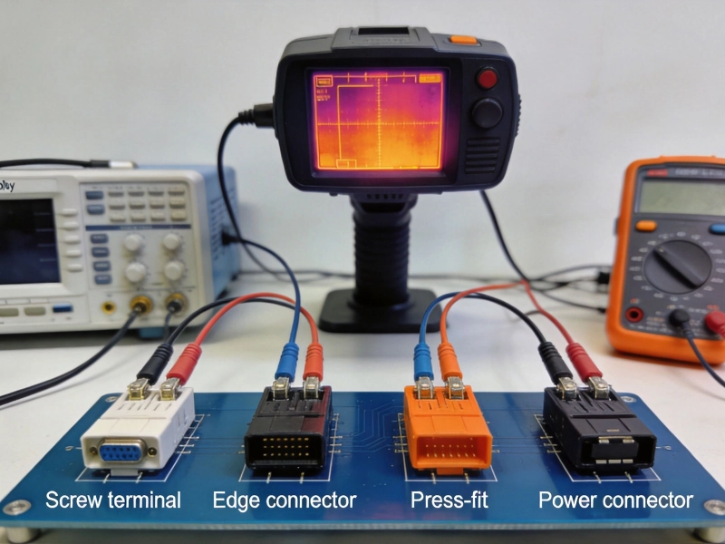
High Current PCB Connector Selection: Test Results and Real Performance DataMay/21/2026
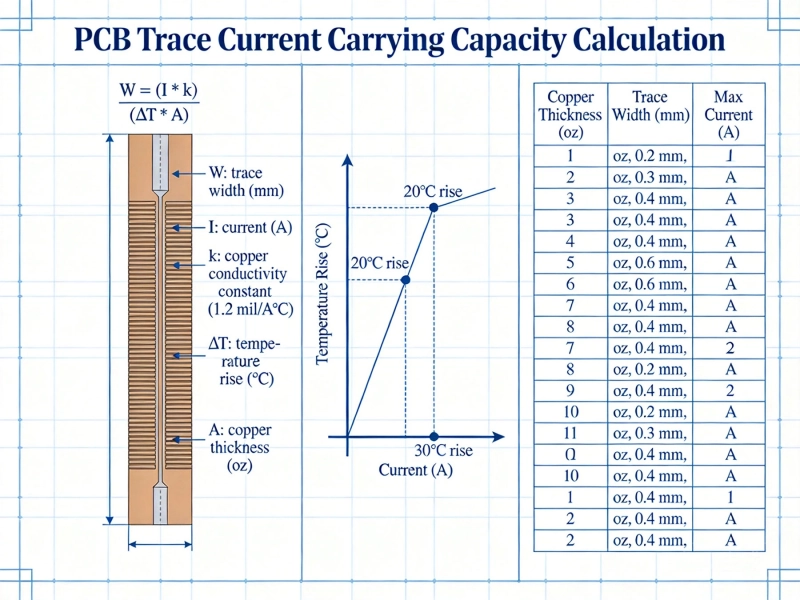
IPC-2152 Current Carrying Capacity: The Definitive PCB Trace Calculator GuideMay/21/2026
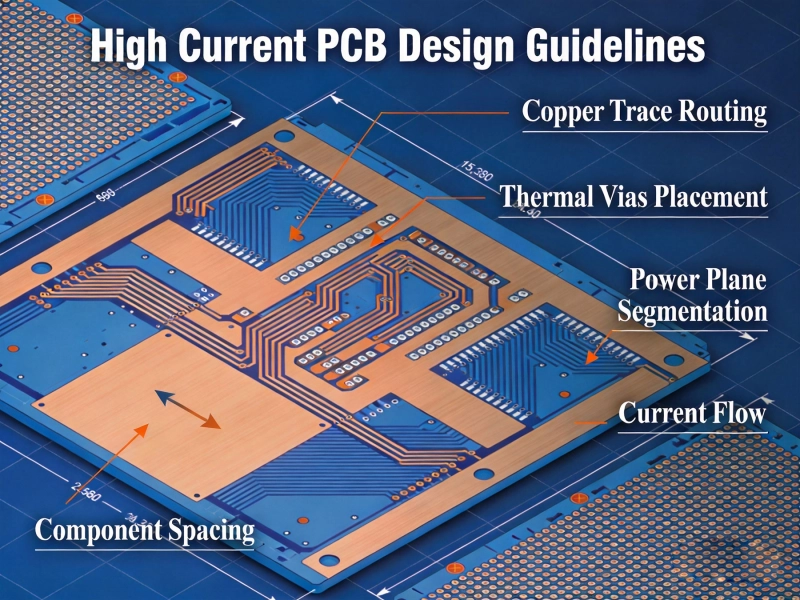
High Current PCB Design GuidelinesMay/21/2026
How Much Current Can a PCB Trace Carry? Complete Engineering GuideMay/20/2026
High Current PCB Connector Selection Guide: Choosing the Right Power Connectors for Your Electronics ProjectsJune/12/2026
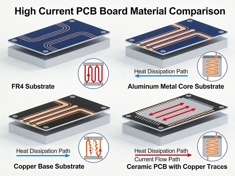
Best Material for High Current PCB Design: How to Choose the Right SubstrateJune/05/2026
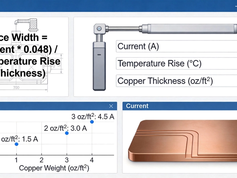
High Current PCB Trace Width Calculator: The Ultimate Engineering GuideMay/20/2026
High Current PCB Failure Modes and PreventionJune/18/2026