
Practical Thermal Management solutions that work, explained by engineers who've been there
Picture this: You've designed what looks like a solid power supply. Clean layout, proper component selection, everything by the book. Then during testing, you notice something troubling. One MOSFET is running at 140°C. That's not a typo.
At that temperature, your component isn't going to last. The Arrhenius equation tells us that for every 10°C above rated temperature, component lifespan roughly halves. A part rated for 100,000 hours at 85°C? At 125°C, you're looking at maybe 30,000 hours. Failures start happening in months, not years.
We see this happen constantly. Engineers spend weeks optimizing efficiency, ripple, and transient response, then treat Thermal Design as an afterthought. The result? Field failures, warranty claims, and products that work perfectly in the lab but fail spectacularly in the real world.
This guide isn't about theory. It's about what actually works when you're under deadline pressure and need Thermal Management that performs.
Before we fix the problem, we need to understand where the heat originates. Most high-power PCBs have five main heat sources:
Quick Math: A "100W" power supply delivering 90W has 10W of losses. That 10W must go somewhere. If not managed, it accumulates and temperatures spike.
Here's what works. After testing hundreds of designs, these five approaches consistently deliver results.
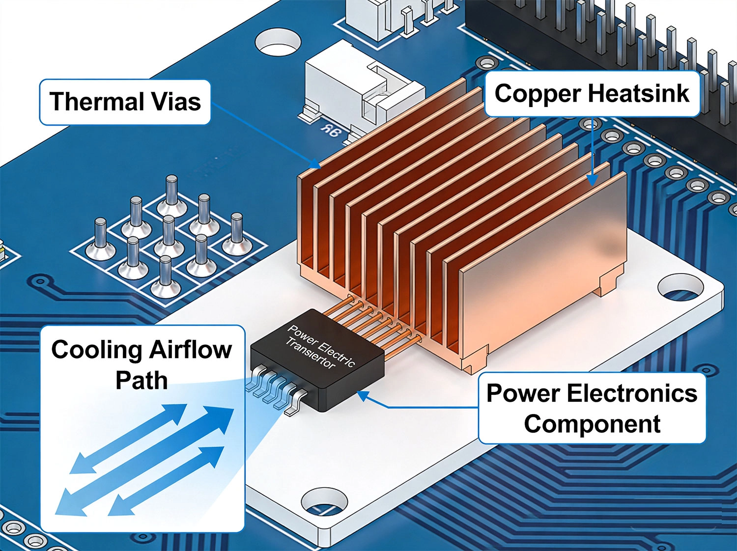
Thermal Vias are probably the most underutilized tool in thermal management. Most designers use a handful and wonder why temperatures stay high. The key? Generosity.
Each thermal via acts like a tiny heat pipe, conducting heat from one layer to another. But here's the thing — one via won't cut it. You need arrays.
What actually works:
The numbers: One 0.3mm via gives you roughly 250°C/W thermal resistance. Ten vias in parallel? About 25°C/W. For a 5W component, that's a 125°C difference. That's the gap between failure and survival.
Copper isn't just for electricity. With thermal conductivity of 400 W/m·K (versus 0.3 W/m·K for FR-4), your copper planes are also massive heat spreaders.
The trick is making sure you're actually using them thermally, not just electrically.
Make copper work harder:
One design we worked on had a MOSFET sitting on an isolated copper island. Moving that island to connect directly to the main ground plane dropped junction temperature by 25°C. No extra cost. Just better connectivity.
Standard FR-4 has thermal conductivity of about 0.3 W/m·K. That's essentially a thermal insulator. But you have better options.
| Material | Conductivity | When to Use |
|---|---|---|
| Standard FR-4 | 0.3 W/m·K | Low power, cost-sensitive |
| High-Tg FR-4 | 0.4-0.5 W/m·K | Higher temp environments |
| Thermal FR-4 | 1-2 W/m·K | Power Electronics |
| Metal-core | 200-400 W/m·K | LED arrays, extreme power |
Copper Weight matters too: Going from 1 oz to 2 oz roughly doubles your thermal capacity. Yes, it costs more, but in power applications, it's almost always worth it. The PCB becomes a more effective heat spreader, reducing or even eliminating heatsink requirements.
Sometimes PCB-level solutions aren't enough. That's when heatsinks enter the picture.
But here's what many engineers miss: the thermal interface material (TIM) between component and heatsink is just as important as the heatsink itself.
TIM comparison:
Heatsink Mounting basics:
Natural convection maxes out around 10-15 W per square inch of surface area. For higher power densities, you need forced air.
Fans aren't complicated, but they do require thoughtful design:
One power supply we troubleshot had perfect Thermal Design in the lab. Field units were failing within months. Turned out the dust filter was never cleaned. Six months of operation had reduced airflow by 70%. Added a filter maintenance indicator and the problem disappeared.
A customer brought us a 500W motor controller design. Initial testing showed junction temperatures of 130°C at just 40°C ambient. Components were derating fast.
What we did:
Result: Junction temperature dropped to 92°C at 40°C ambient. The design passed extended burn-in testing and went into production with zero thermal-related field failures in the first year.
Industrial LED driver, 100W total. LEDs were junction-limited to 105°C maximum. At 35°C ambient with natural convection, our initial layout showed 108°C. One degree over limit, guaranteed field failures.
What we did:
Result: Junction temperature dropped to 82°C at 35°C ambient. LEDs running cool meant longer lifetime, better lumen maintenance. The slightly higher PCB cost was easily justified by the extended warranty we could now offer.
Simulation is great. Real testing is essential. Here's what we recommend:
Tools like Ansys Icepak, Mentor FloTHERM, and even built-in CAD thermal analyzers can predict temperatures reasonably well. Use them early in design to identify problems before layout is complete.
But don't trust simulation alone. Real hardware always surprises you. The thermal conductivity of your specific PCB material, the actual mounting pressure on that heatsink, the thermal resistance of your TIM batch — all these vary from simulation assumptions.
Rule of thumb: If simulation and testing disagree, trust testing. Then update your simulation models to match reality.
Your motor driver "typically" draws 8A. So you size traces for 8A. Then the motor stalls and pulls 18A. Surprise — burned traces.
Fix: Always design for peak current. Include in-rush, stall conditions, and fault scenarios.
You've got a 200 mil trace carrying 10A. But at the IC pad, it connects through a single 0.3mm via. That via becomes the bottleneck — and possibly a fuse.
Fix: Use multiple vias for any high-current transition. Rule of thumb: one standard via per 2A.
Works beautifully at 22°C. Fails catastrophically at 45°C. This is the most common thermal-related field failure pattern.
Fix: Test at maximum specified ambient temperature. Not as an afterthought. As part of your standard test procedure.
In low-voltage systems, trace resistance causes voltage drop that can be more limiting than temperature rise.
Fix: Calculate voltage drop for all power traces. A 100mV drop on a 5V rail is 2% loss — potentially significant.
Here's the shift that eliminates most thermal problems: treat thermal design as a first-class requirement, not an optimization.
What this means in practice:
This adds maybe a few hours to your design process. It saves weeks of debugging, respins, and field failures.
We've seen the pattern repeat dozens of times: engineers who integrate thermal thinking from the start have reliable products. Those who treat it as an afterthought have warranty claims.
For most power components, start with a 5×5 array under thermal pads. Add more if temperatures exceed budget. You can also have too many — dense via arrays can weaken mechanical joints. For very high power, 10×10 or more isn't unusual. For standard ICs, 3×3 minimum.
For production, pads are usually better. Consistent application, no mess, predictable performance. Grease gives slightly better thermal performance but requires more process control. Use grease when thermal performance is critical and you can control application quality. Use pads for most production scenarios.
Maybe. An enclosure raises ambient temperature significantly — sometimes 20-30°C higher than outside air. It also restricts airflow. Test in the actual enclosure, or at least in a mockup with similar thermal characteristics. Open-air testing is a starting point, not validation.
When power density is very high and standard FR-4 can't provide sufficient thermal spreading. LED arrays, high-current motor drivers, and extreme-power converters are typical applications. Metal-core costs more, so use it when the performance benefit justifies the expense. For most Power Electronics, good FR-4 design with thermal vias and heavy copper is sufficient.
Work backwards from your temperature budget. If component max junction is 150°C, ambient is 40°C, and component-to-heatsink thermal resistance is 2°C/W, you have (150-40-2×Power) for heatsink budget. Divide remaining temperature budget by power to get maximum heatsink thermal resistance. Select heatsink at or below that value, then verify with testing.
Several approaches: temperature monitoring with automatic shutdown, redundant fans, larger passive heatsink that handles emergency cooling, or thermal fuses that cut power if temperatures exceed safe limits. For critical applications, redundant cooling isn't optional — it's required.
Thermal management isn't complicated. It's just often treated as an afterthought when it should be a primary consideration.
The engineers who consistently build reliable power electronics share one habit: they think about heat from the beginning. They calculate expected dissipation, set temperature budgets, and design thermal paths before they start layout.
It's not about being perfect. It's about being systematic. Follow the five methods we covered — thermal vias, copper pours, smart material selection, proper heatsinking, and active cooling when needed — and you'll eliminate 90% of thermal problems before they occur.
Save the thermal imaging and debugging for the edge cases. The fundamentals we've outlined here will carry you through most designs.
Now get out there and build something that doesn't melt.
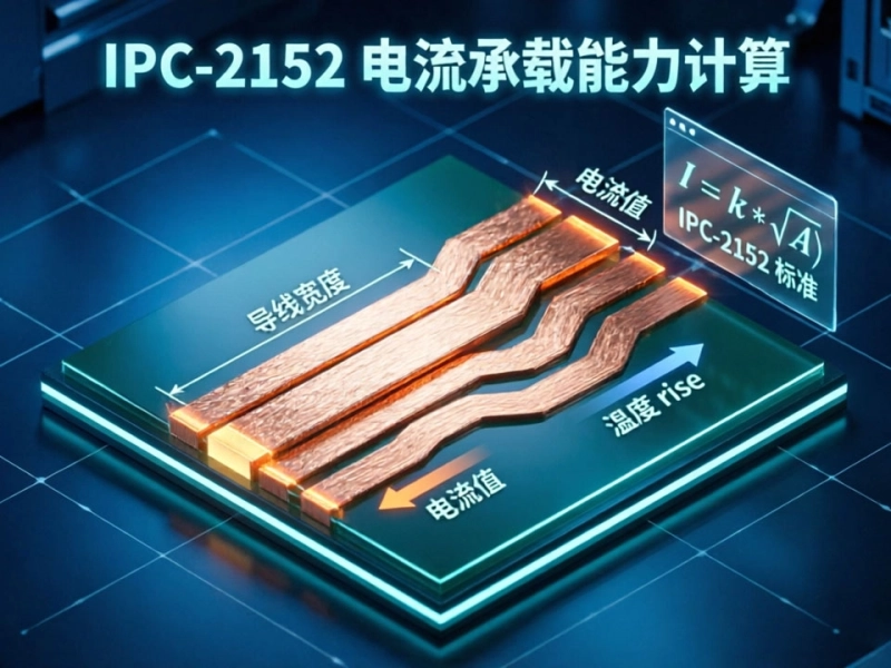
Mastering IPC-2152 Current Carrying Capacity Calculation for Reliable PCB DesignJune/04/2026
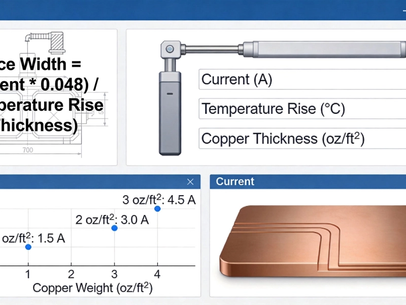
High Current PCB Trace Width Calculator: The Ultimate Engineering GuideMay/20/2026
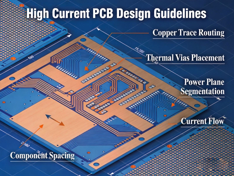
High Current PCB Design GuidelinesMay/21/2026
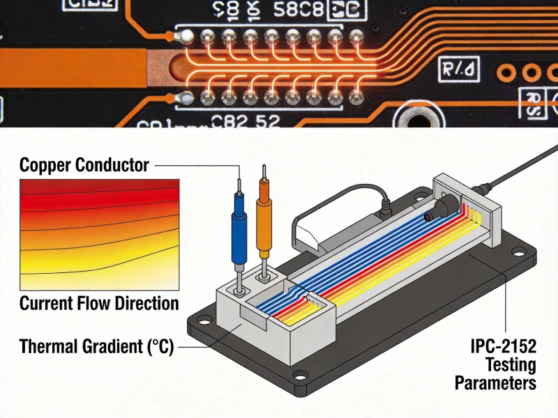
IPC-2152 Current Carrying Capacity Calculation GuideJune/03/2026

5 Critical Thermal Management Problems in High Power PCBsMay/21/2026
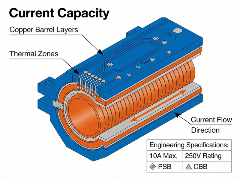
Plated Through Hole Current Rating: Complete Guide for PCB DesignersMay/21/2026
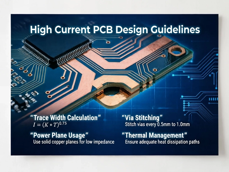
High Current PCB Design Guidelines: Ensuring Reliability and SafetyJune/08/2026
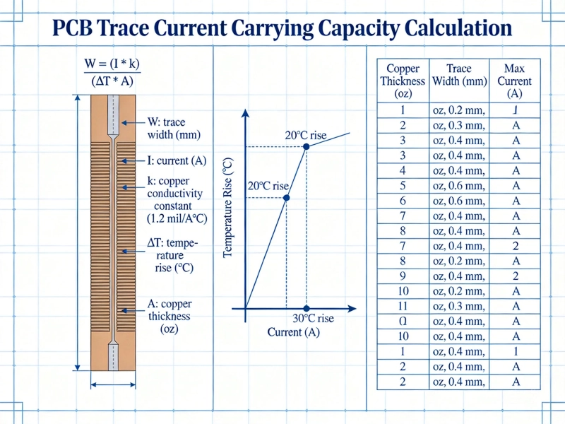
IPC-2152 Current Carrying Capacity: The Definitive PCB Trace Calculator GuideMay/21/2026