

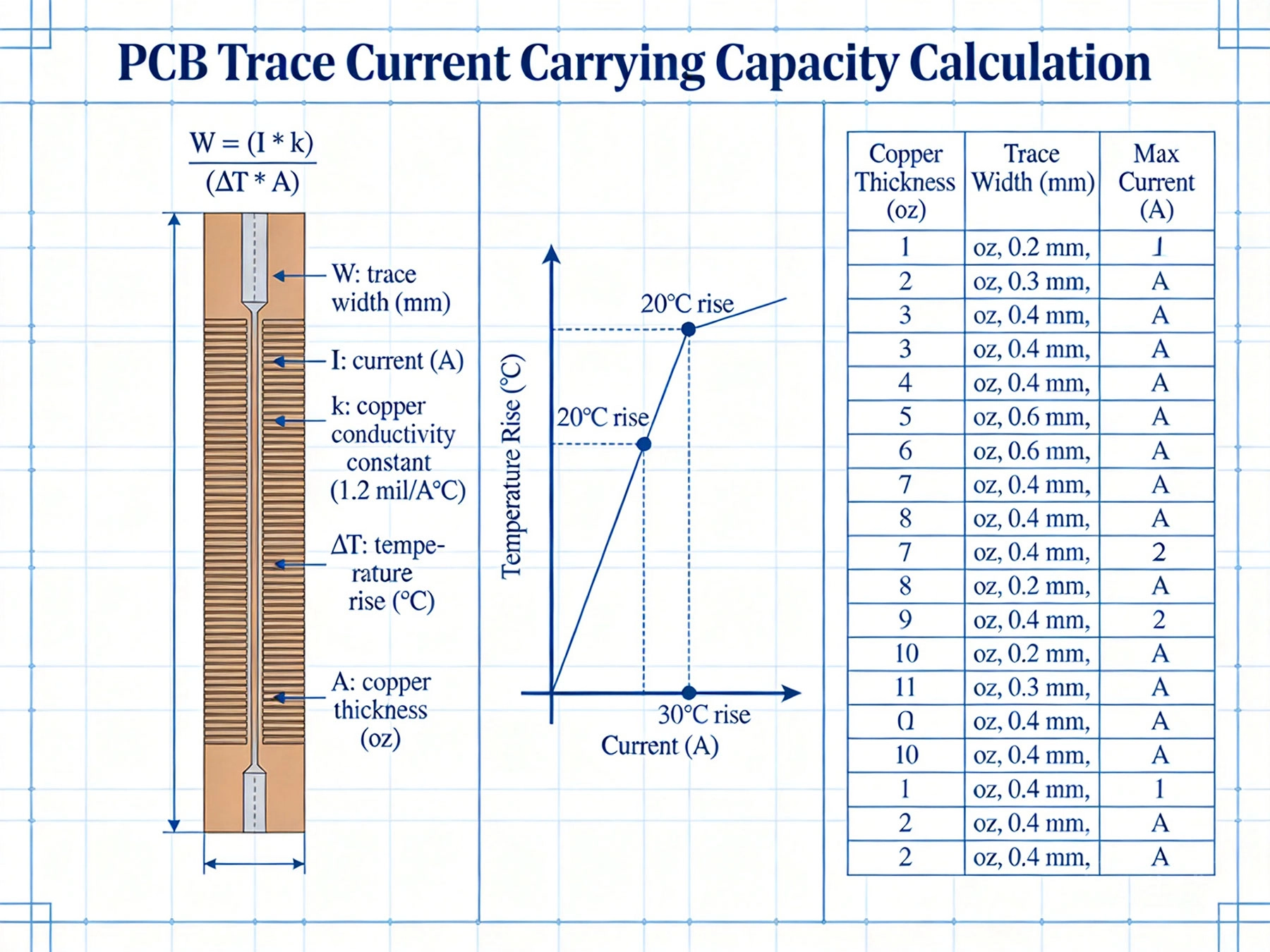
Why smart engineers stopped using trace width calculators—and started understanding the physics Why IPC-2152 Changes Everything For decades, PCB designers relied on IPC-2221 (formerly MIL-STD-275) trace width charts. The problem? ...
https://www.high-current-pcb.com/high-current-pcb-dfm-tips/ipc-2152-current-carrying-capacity-the-definitive-pcb-trace-calculator-guide/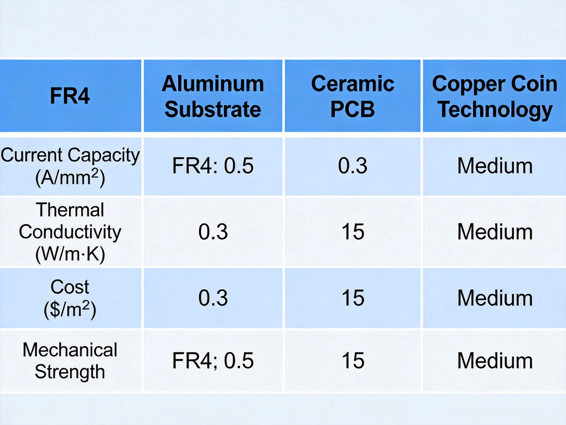
A practical selection guide based on current capacity, thermal needs, and budget constraints The Material Choice Dilemma I once spent three weeks redesigning a 100A motor controller because I chose the wrong PCB material. Standard FR-4...
https://www.high-current-pcb.com/high-current-pcb-materials-standards/best-material-for-high-current-pcb-design/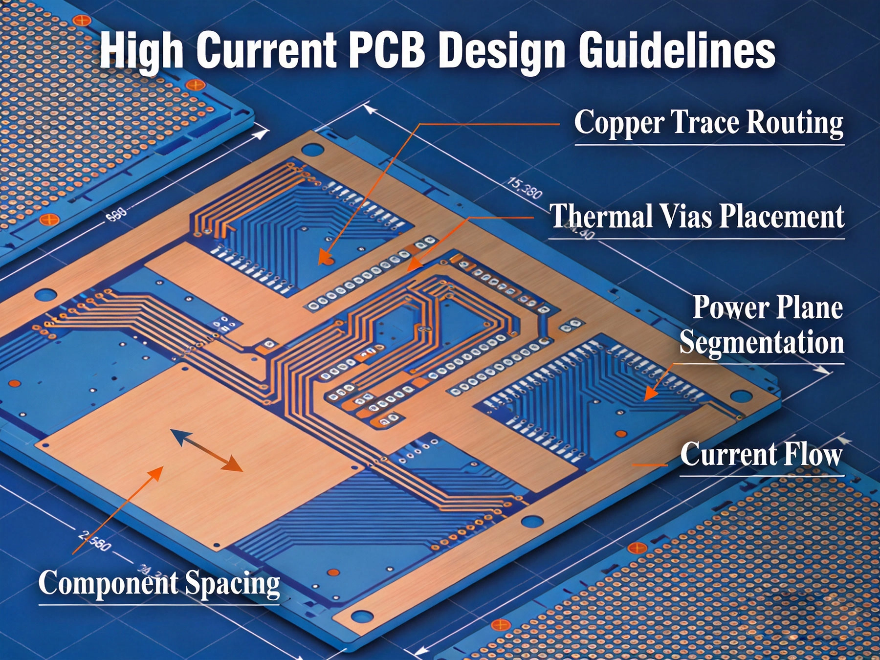
Everything you need to design reliable power electronics—from trace widths to thermal management What You'll Learn in This Guide Calculate trace widths for any current requirement Master thermal vias and heat dissipation t...
https://www.high-current-pcb.com/high-current-pcb-thermal-design/high-current-pcb-design-guidelines/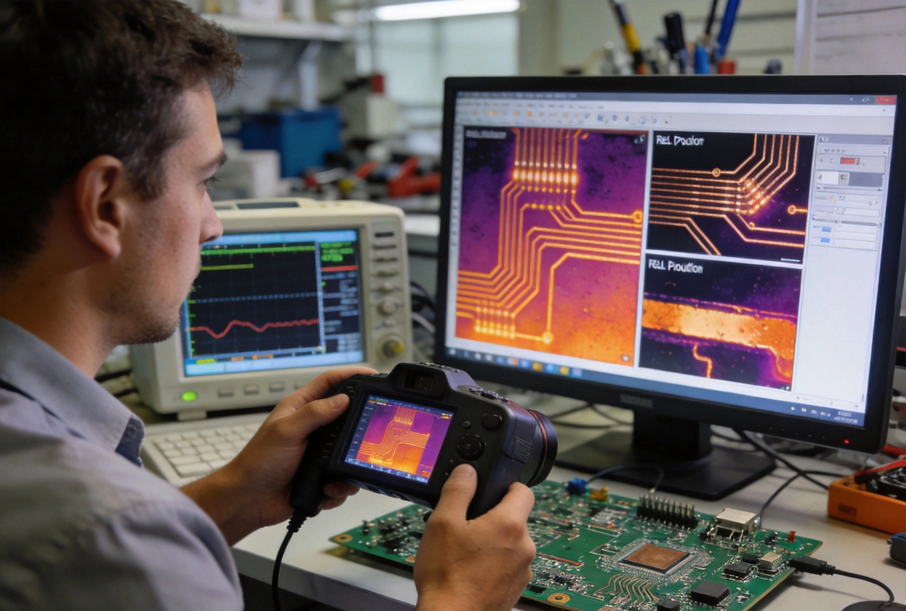
Real production failure analysis from 50+ power electronics projects. The data surprised us. The Shocking Finding After analyzing 47 production PCB failures from 2019-2024, we discovered something unexpected: boards with copper pour fa...
https://www.high-current-pcb.com/high-current-pcb-manufacturing-tech/copper-pour-vs-trace-what-3-years-of-pcb-failures-taught-us/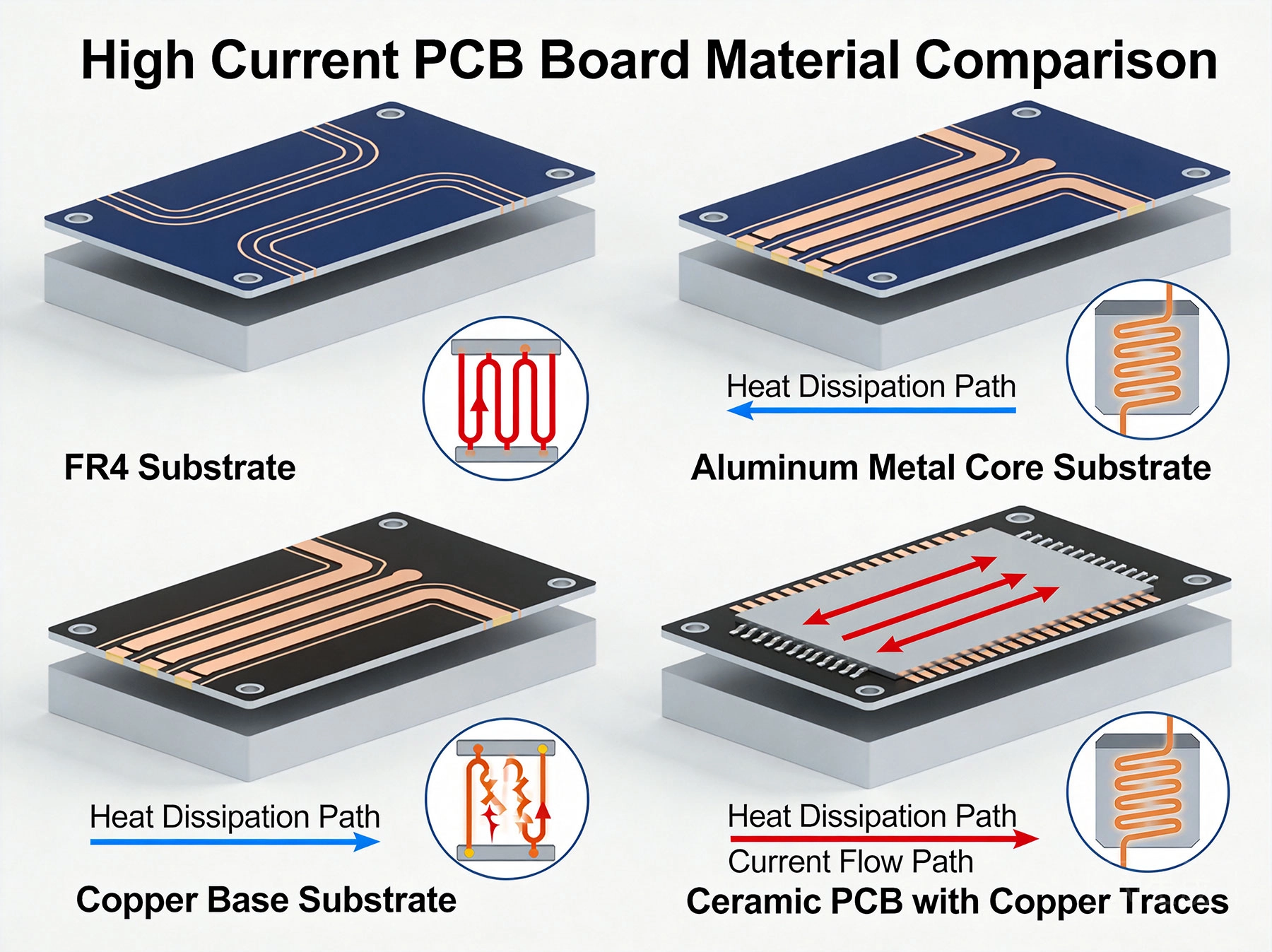
Power electronics are everywhere—from electric vehicle charging stations to industrial motor drives, from solar inverters to server power supplies in data centers. These systems transmit large currents, and heat is generated when current flows thro...
https://www.high-current-pcb.com/high-current-pcb-materials-standards/best-material-for-high-current-pcb-design-how-to-choose-the-right-substrate/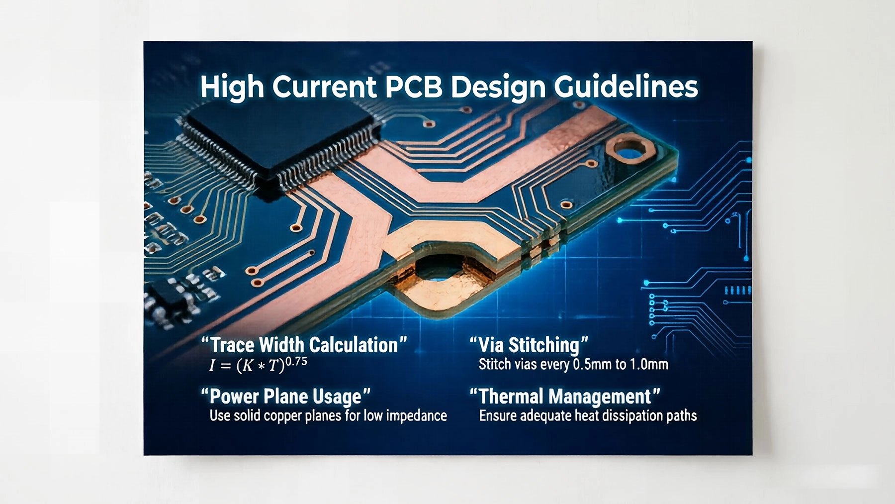
Designing Printed Circuit Boards (PCBs) for high-current applications requires a distinct approach compared to standard signal-level designs. Whether you are building power supplies, motor controllers, or battery management systems, managing heat a...
https://www.high-current-pcb.com/high-current-pcb-thermal-design/high-current-pcb-design-guidelines-ensuring-reliability-and-safety/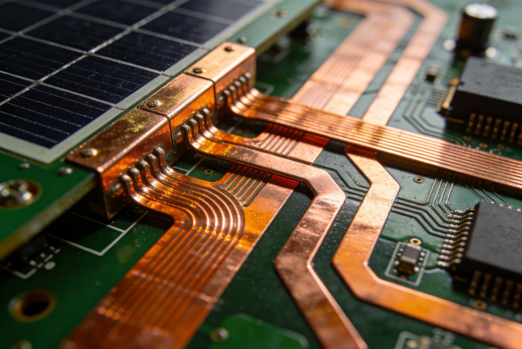
Solar inverters operate at the heart of photovoltaic systems, converting DC power from panels into AC power for homes and grids. This conversion process demands PCB designs that can handle substantial current flows — sometimes exceeding 50 or even ...
https://www.high-current-pcb.com/high-current-pcb-thermal-design/a-deep-dive-into-high-current-pcb-design-for-solar-inverters/
Designing printed circuit boards for high current applications demands precision in trace width calculations. The copper conductors that carry power through your PCB must dissipate heat while maintaining structural integrity and avoiding voltage dr...
https://www.high-current-pcb.com/industrial-automation/high-current-pcb-trace-width-ipc-2152-calculator-vs-empirical-formulas/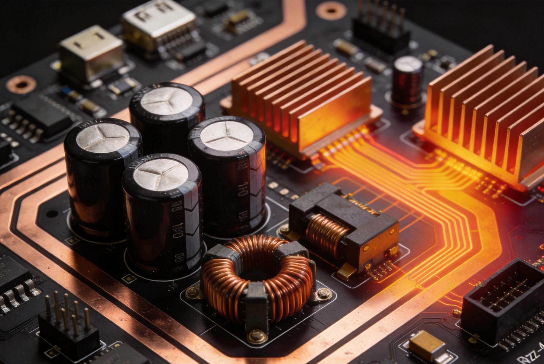
Designing high-current PCBs presents challenges that go far beyond standard digital electronics. When your board must handle tens or hundreds of amperes, every placement decision impacts thermal performance, electromagnetic interference, and system...
https://www.high-current-pcb.com/industrial-automation/high-current-pcb-component-placement-grouping-vs-distributed-layout/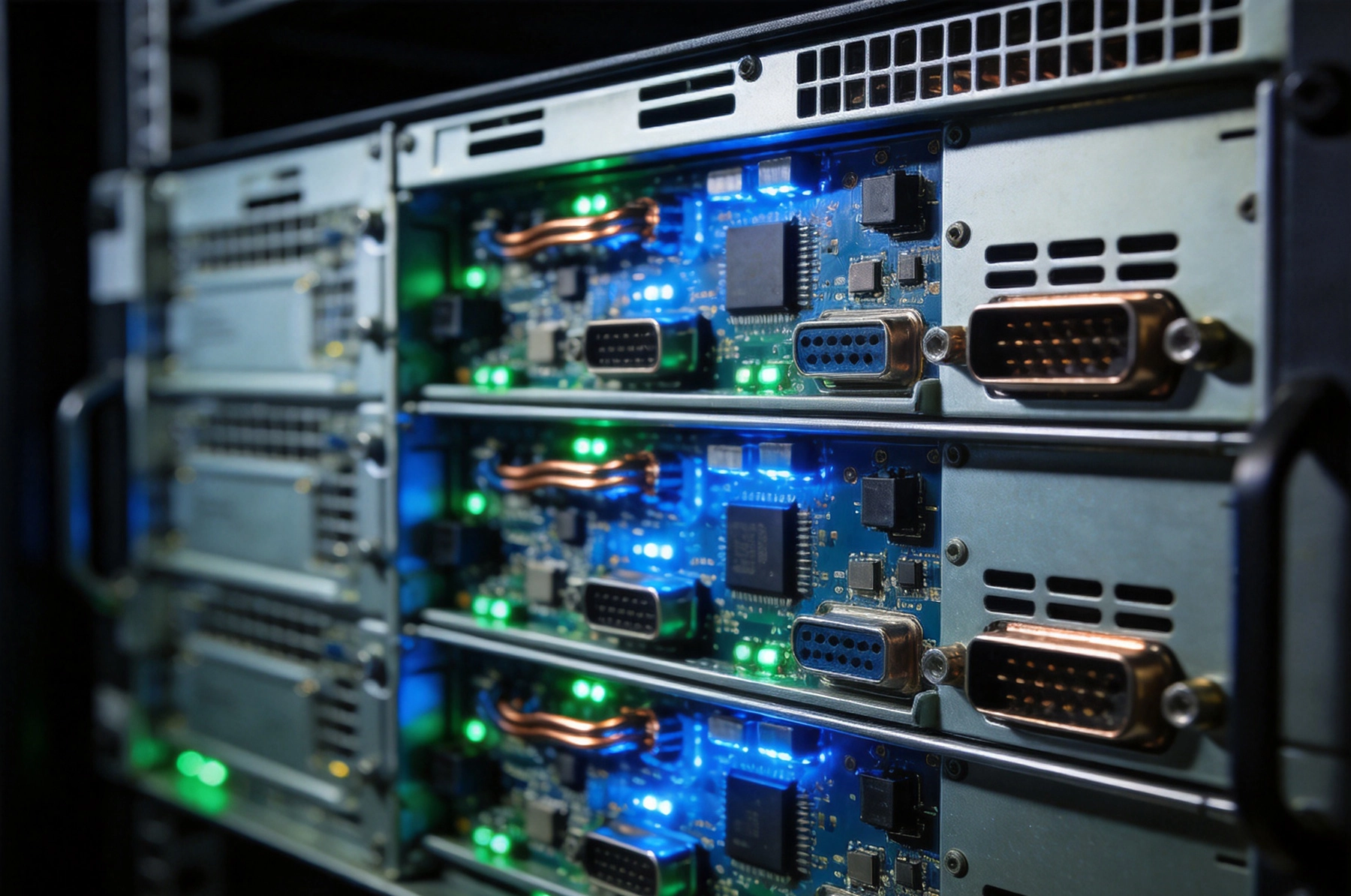
Server racks today demand more power than ever before. A single high-density rack can house hundreds of blade servers, storage arrays, network switches, and power distribution units that collectively draw tens of kilowatts. At the heart of deliveri...
https://www.high-current-pcb.com/high-current-pcb-manufacturing-tech/building-a-high-current-pcb-power-supply-for-server-racks/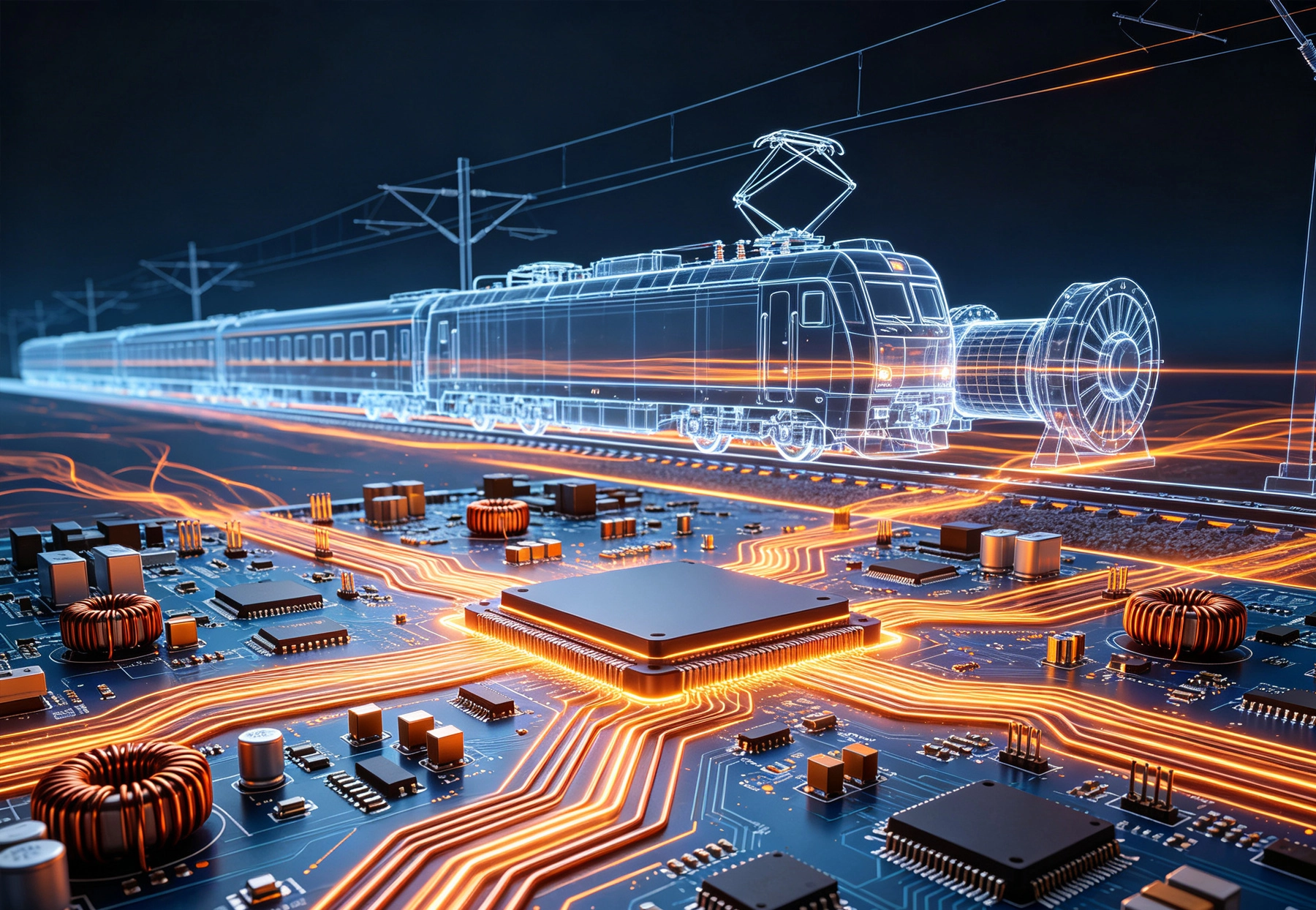
Railway traction systems represent some of the most demanding applications for power electronics. These systems control massive electric motors that propel trains, trams, and high-speed rail vehicles, requiring PCB designs capable of handling hundr...
https://www.high-current-pcb.com/high-current-pcb-thermal-design/high-current-pcb-design-for-railway-traction-systems/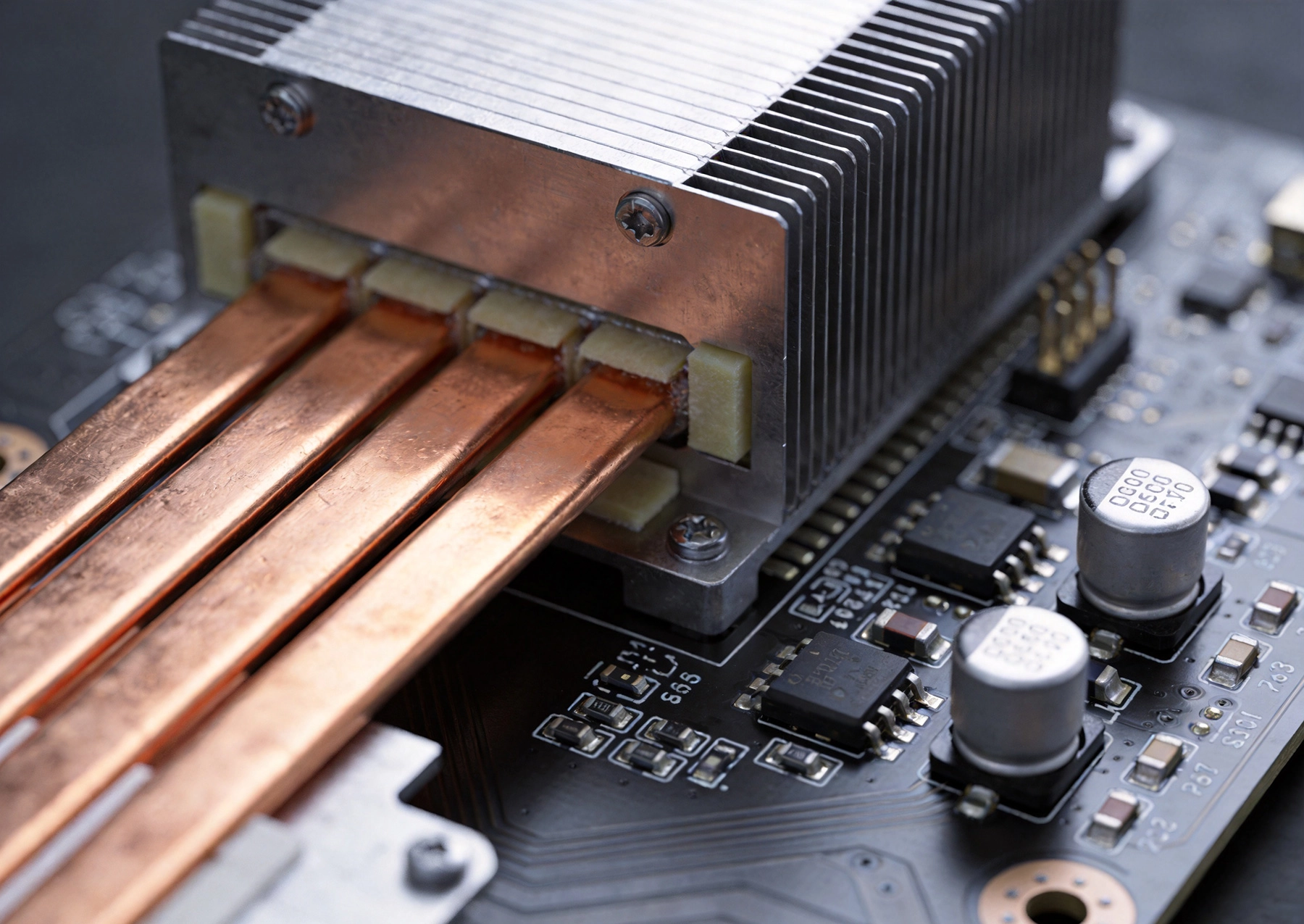
Power electronics designers face critical thermal management decisions when dealing with high current PCB applications. Choosing between thermal interface pads and direct copper exposure for heat sink attachment significantly impacts thermal perfor...
https://www.high-current-pcb.com/aerospace-defense-avionics/high-current-pcb-heat-sinks-thermal-pads-vs-direct-copper-exposure/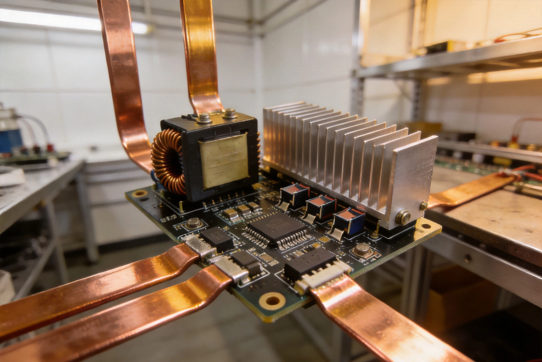
High-power LED applications demand robust PCB design strategies that can handle substantial current loads while maintaining thermal efficiency and electrical reliability. As LED technology continues to advance, drivers must deliver increasingly hig...
https://www.high-current-pcb.com/high-current-pcb-thermal-design/high-current-pcb-design-for-high-power-led-drivers/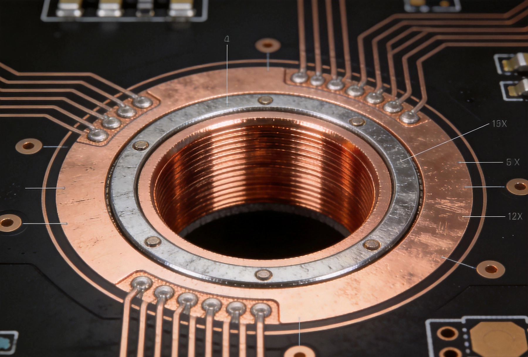
In high-current PCB design, every detail matters when it comes to ensuring reliability and performance. The annular ring, the copper pad surrounding a plated through-hole, plays a critical role in both electrical connectivity and mechanical integri...
https://www.high-current-pcb.com/high-current-pcb-dfm-tips/high-current-pcb-annular-rings-minimum-size-vs-reinforced-size/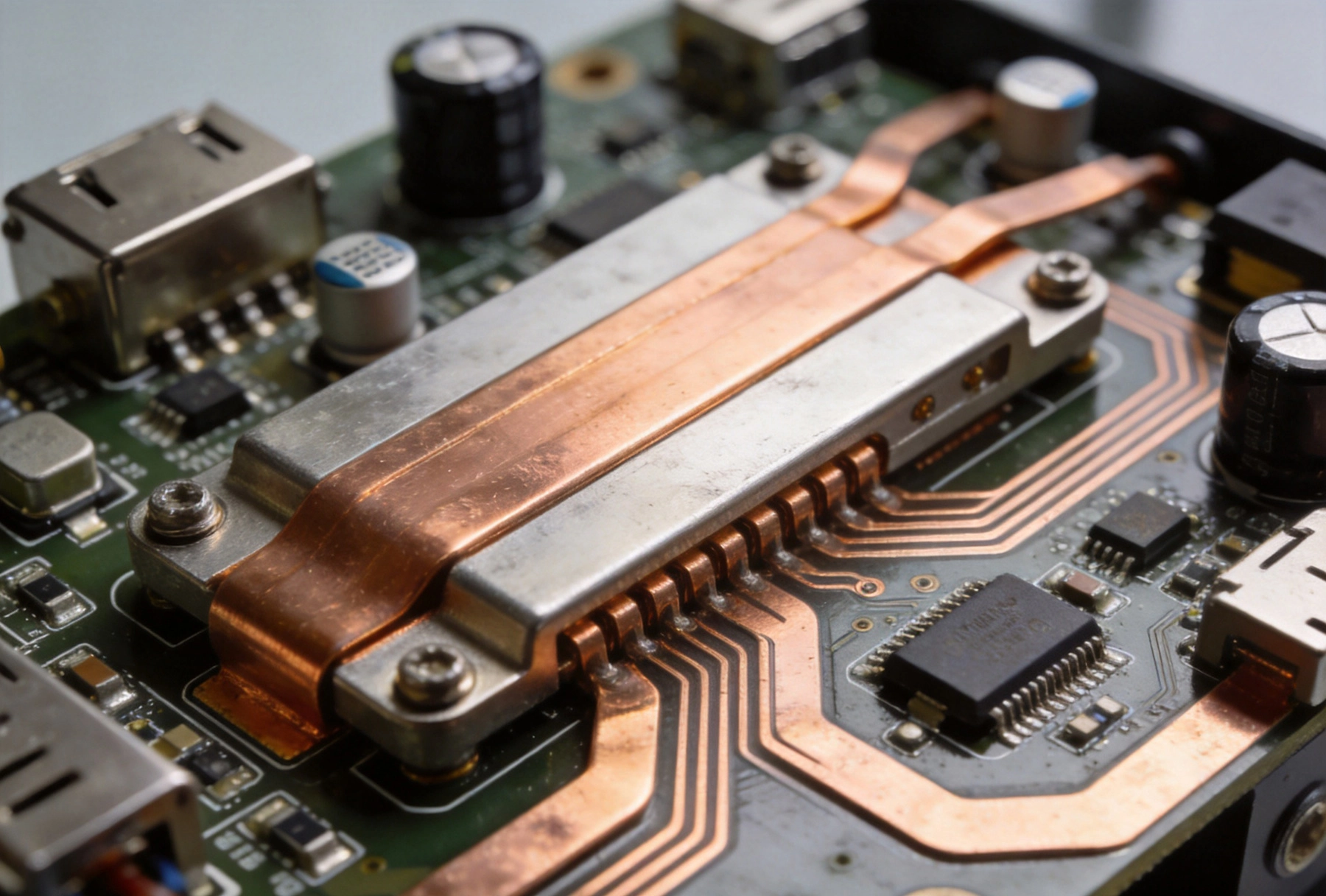
The rapid growth of electric vehicle adoption has created unprecedented demand for reliable, high-power charging infrastructure. At the heart of every EV charging station lies a sophisticated power electronics system, with printed circuit boards se...
https://www.high-current-pcb.com/high-current-pcb-thermal-design/high-current-pcb-design-for-electric-vehicle-charging-stations/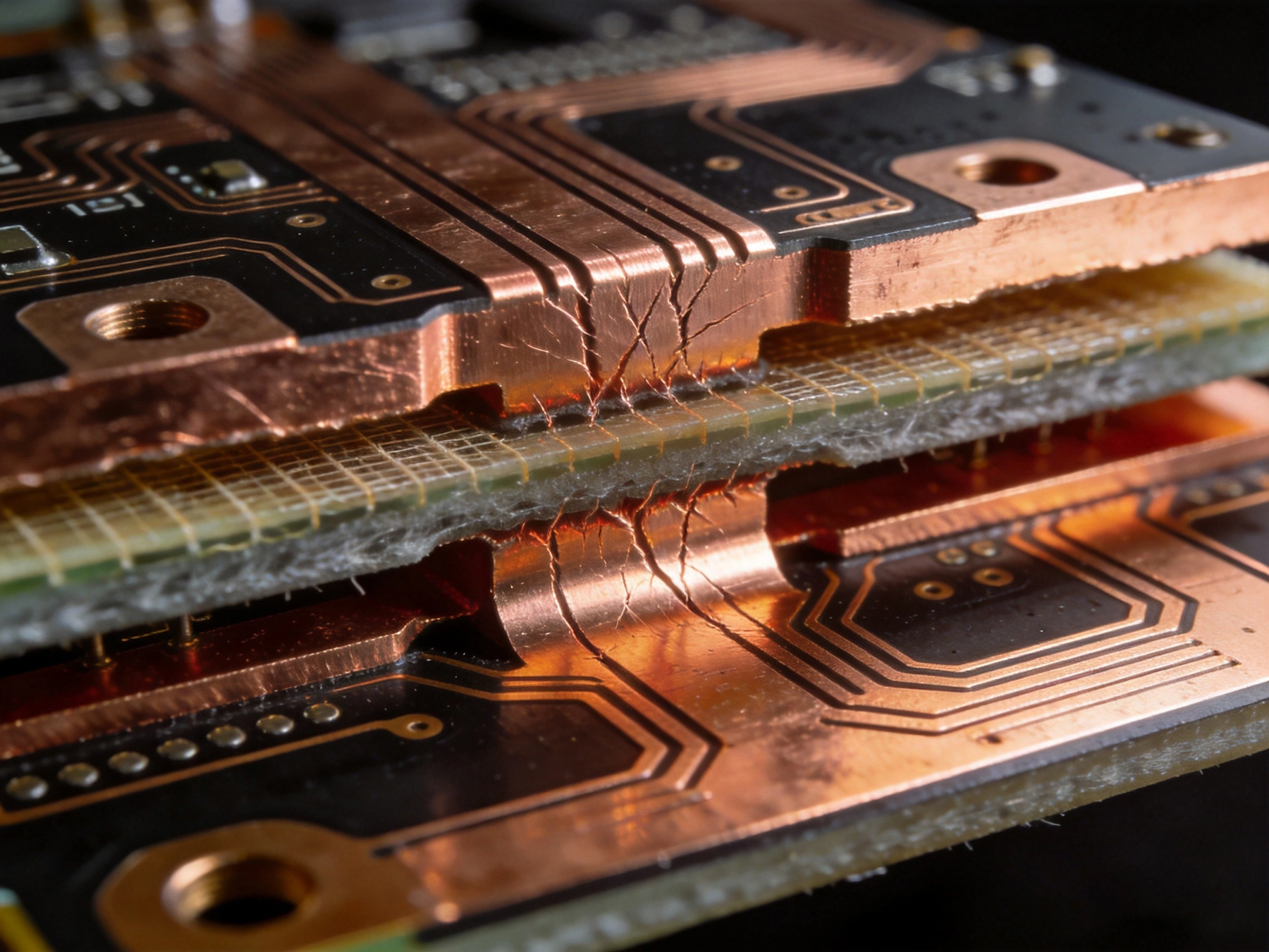
Heavy copper PCBs power everything from electric vehicle chargers to industrial motor drives, carrying currents that would destroy standard circuit boards. Yet the very copper that makes these boards capable of handling high amperage also creates o...
https://www.high-current-pcb.com/high-current-pcb-basics/high-current-pcb-copper-balancing-preventing-warpage-in-heavy-copper-boards/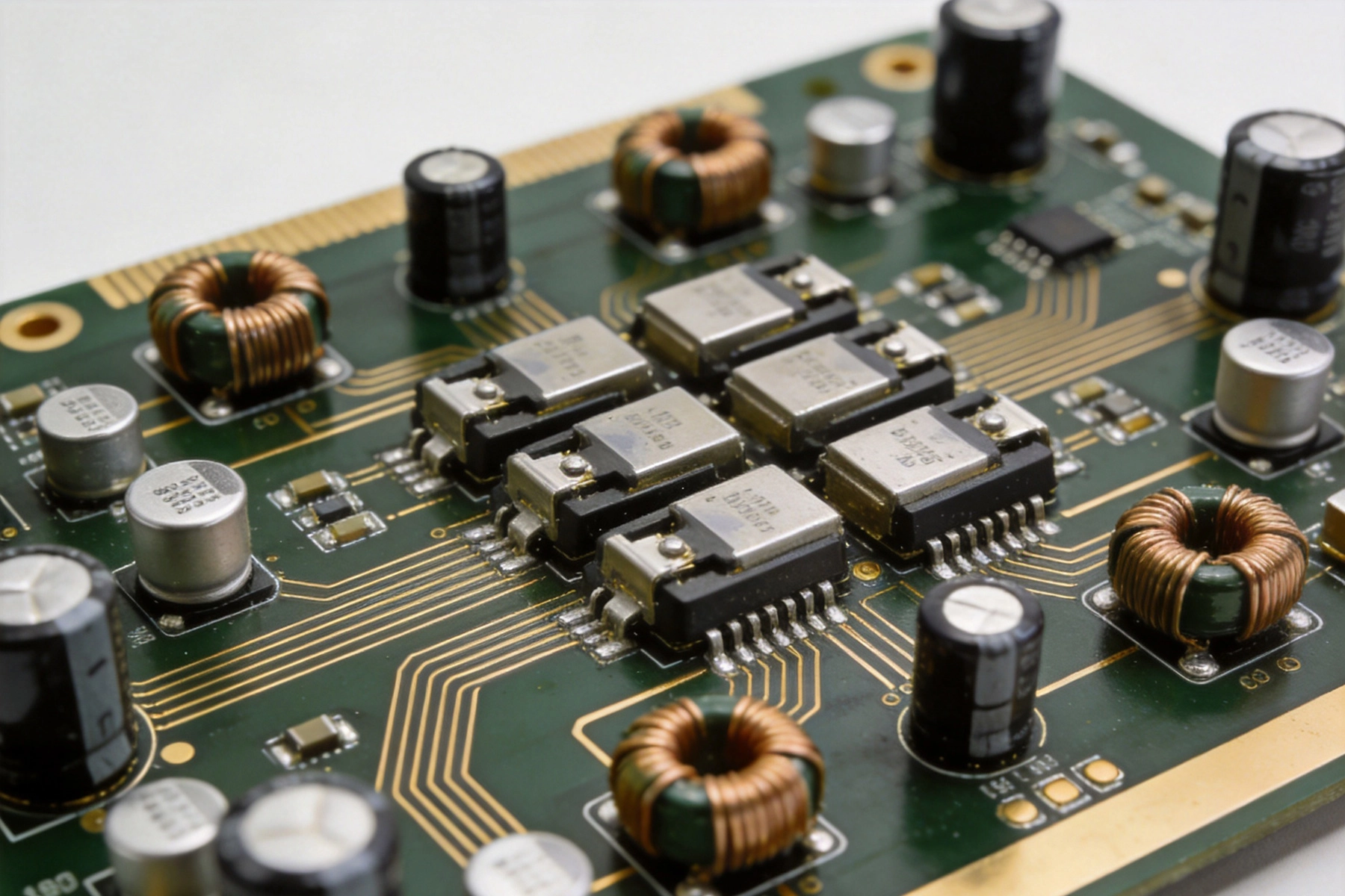
Designing a PCB for a high-current audio amplifier presents unique challenges that go beyond standard PCB layout practices. Audio amplifiers demand both precise low-level signal handling and robust power delivery, all while maintaining absolute sil...
https://www.high-current-pcb.com/high-current-pcb-thermal-design/high-current-pcb-design-for-audio-amplifiers-avoiding-ground-loops/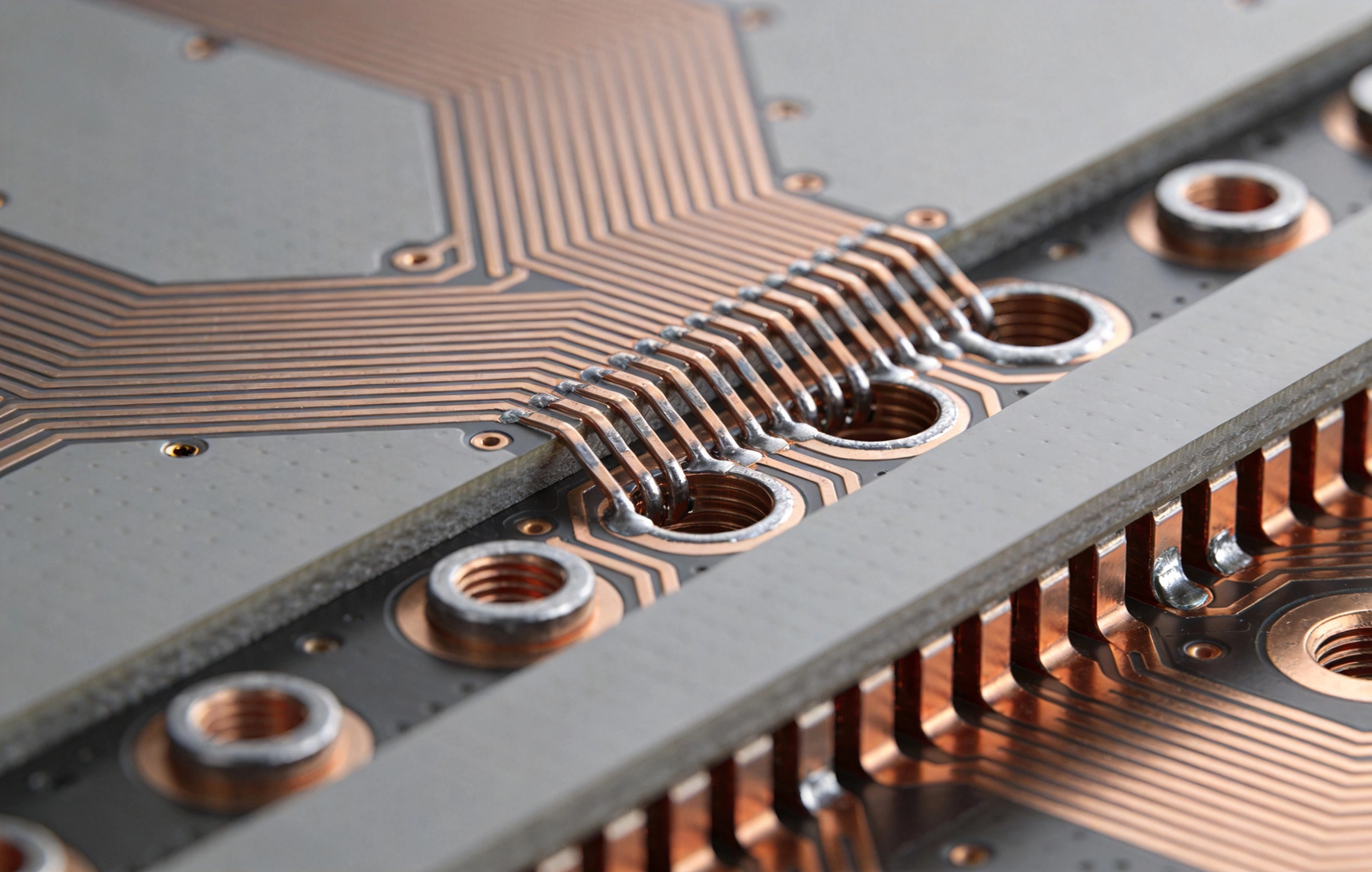
Heat has always been the enemy of electronics. In high current applications, this enemy grows stronger. Components that dissipate significant power generate thermal gradients across circuit boards, and if that heat isn't managed effectively, reliab...
https://www.high-current-pcb.com/high-current-pcb-thermal-design/high-current-pcb-thermal-vias-array-spacing-and-heat-transfer-efficiency/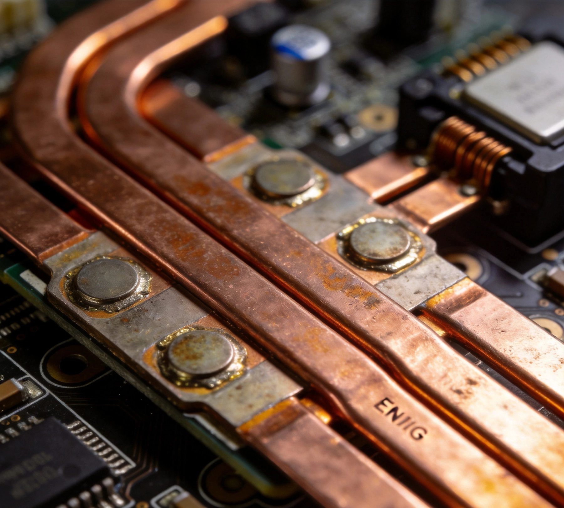
High current PCB design presents unique challenges that standard surface finish selections may not address. When your board needs to carry tens or hundreds of amperes through power traces and pads, surface finish choice affects current carrying cap...
https://www.high-current-pcb.com/telecom-5g-high-speed-computing/high-current-pcb-surface-finish-enig-vs-hasl-for-high-current-pads/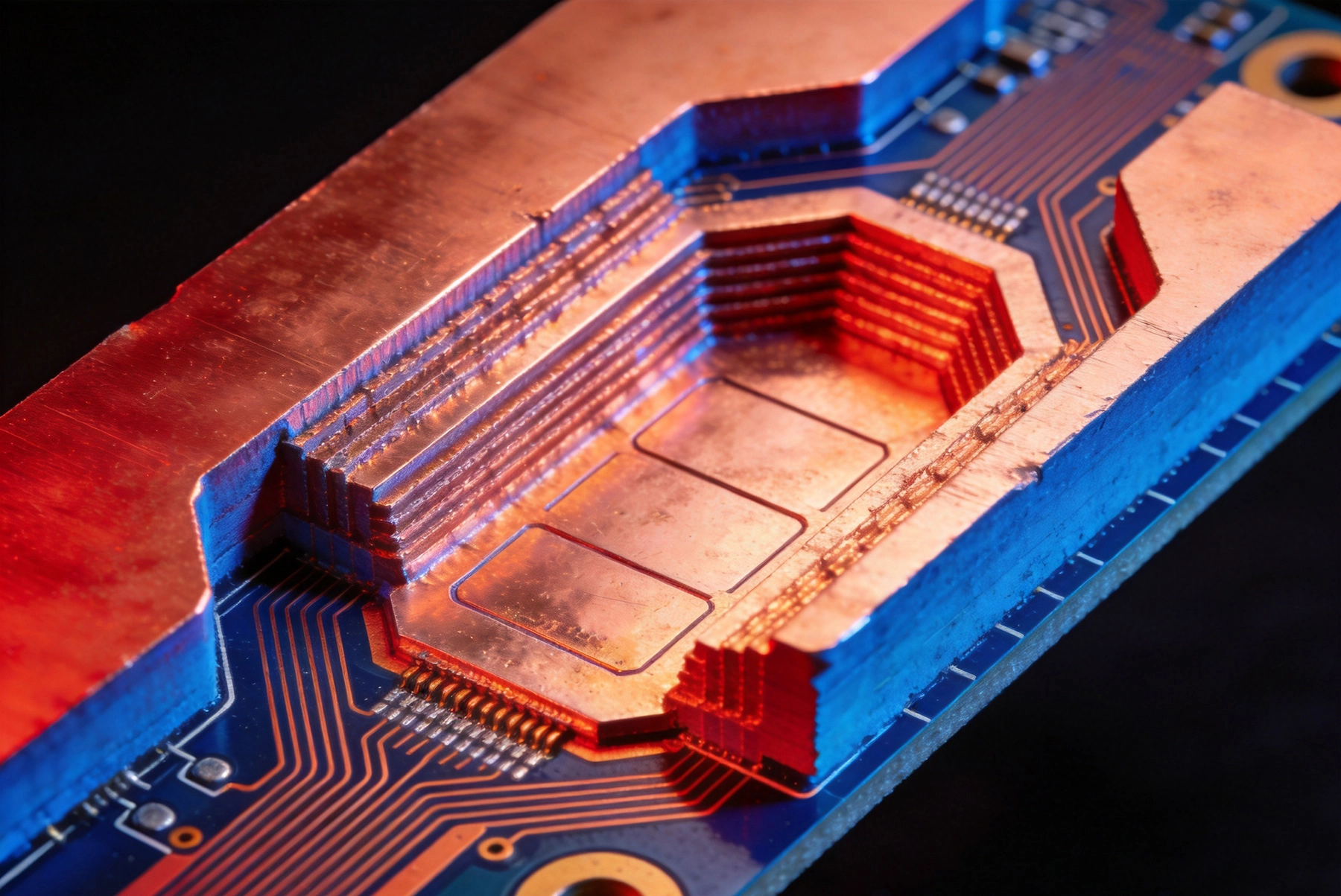
In power electronics, managing heat is as important as managing current. A trace that can carry 20 amps on paper may fail in practice if the heat generated by I²R losses cannot escape the board fast enough. This is where the choice between internal...
https://www.high-current-pcb.com/automotive-ev-systems/high-current-pcb-embedded-copper-internal-vs-external-heat-dissipation/