
Power Electronics are everywhere—from electric vehicle charging stations to industrial motor drives, from solar inverters to server power supplies in data centers. These systems transmit large currents, and heat is generated when current flows through Pcb Traces. If the materials are not properly selected, overheating can lead to performance degradation, shortened lifespan, and even catastrophic failure
Choosing the right PCB material for High Current applications isn't as simple as picking the thickest copper. The substrate—the non-conductive base material—plays a critical role in Thermal Management, mechanical strength, and long-term reliability. This guide breaks down your options so you can make informed decisions for your Power Electronics projects.
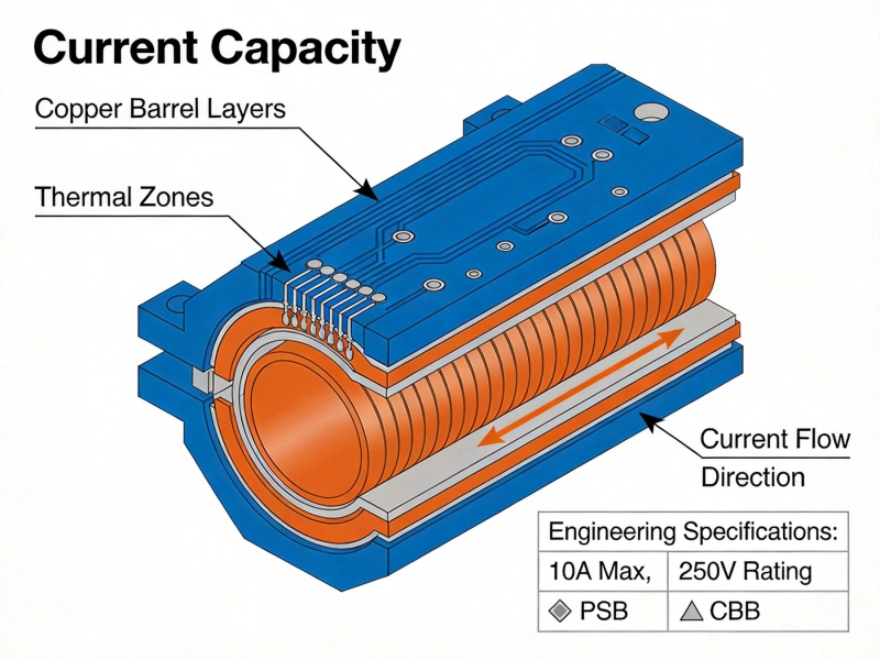
Before diving into materials, let's understand why High Current Pcb Design is challenging. When current flows through a conductor, it encounters resistance. That resistance converts electrical energy into heat through Joule heating (P = I²R). Higher current means exponentially more heat generation.
Beyond basic resistance, High Current designs face several interconnected challenges:
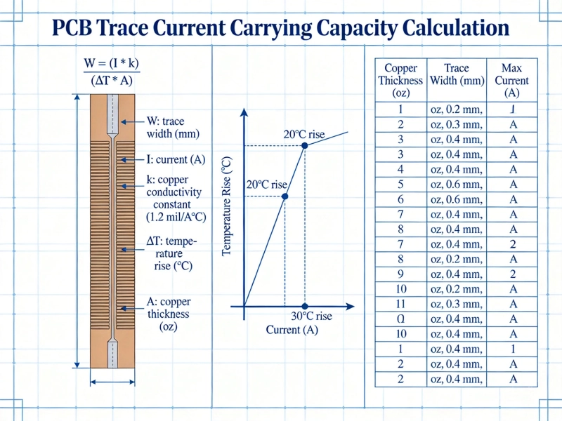
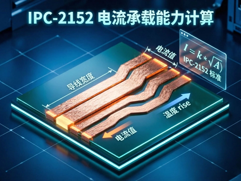
Temperature rise: Pcb Traces carrying current heat up. The Ipc-2221 Standard provides formulas for allowable current based on trace dimensions, but these calculations assume ambient conditions and don't fully account for real-world thermal environments.
Voltage drop: Long current paths waste power as heat. In high current applications, even small resistances matter. A 1mΩ trace carrying 30A drops 30mV—acceptable for some designs, disastrous for others.
Mechanical stress: Thermal expansion mismatch between copper and substrate creates stress during temperature cycles. Repeated heating and cooling can crack traces or delaminate layers over time.
Skin effect: At high frequencies, current concentrates near the conductor surface, effectively reducing cross-sectional area and increasing resistance. This matters for switching power supplies with PWM or high-speed control signals.
Not every PCB material handles high current equally well. The best materials share several characteristics:
High glass transition temperature (Tg): This is the temperature at which the substrate transitions from rigid to flexible. Higher Tg materials maintain structural integrity at elevated temperatures. Standard FR-4 has Tg around 130-140°C, while high-Tg versions reach 170°C or higher.
Thermal conductivity: This measures how efficiently the material transfers heat away from current-carrying traces. Standard FR-4 has thermal conductivity around 0.3 W/m·K—quite poor. Metal substrates offer 10-100x improvement.
Thermal decomposition temperature (Td): Beyond Tg, materials eventually decompose. Td indicates when the substrate begins breaking down chemically. Higher Td means better thermal margin.
Copper adhesion: Strong bond between copper and substrate prevents delamination during thermal cycling. This matters especially for thick copper layers required in high current applications.
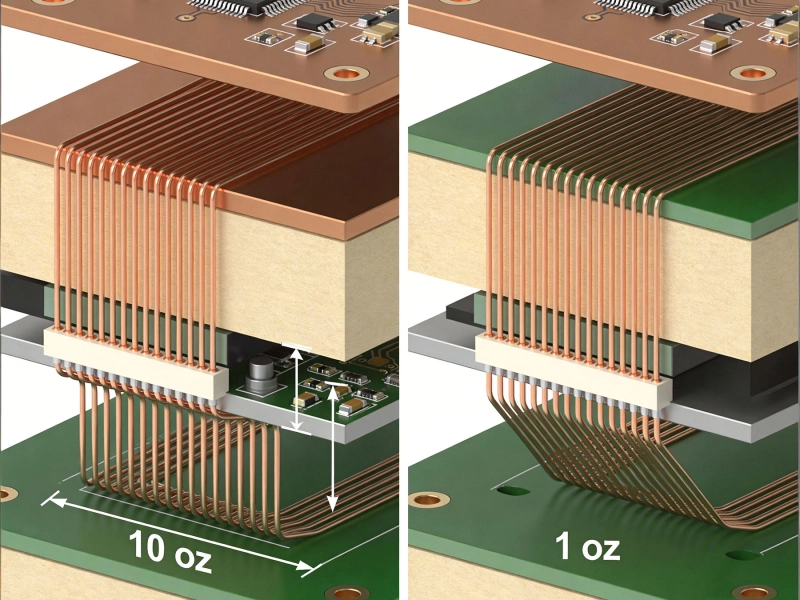
While this guide focuses on substrate materials, Copper Thickness deserves mention because it directly determines current capacity. Standard copper weights:
0.5 oz (17.5 μm): Thin copper for fine-pitch, high-density designs. Not suitable for high current.
1 oz (35 μm): Standard copper weight. Suitable for low to moderate current (up to 2-3A for external traces).
2 oz (70 μm): Heavy copper for moderate current (3-10A per external trace). Common in power supplies.
3 oz (105 μm) and thicker: Required for high current applications (10A+). Some manufacturers offer up to 10 oz copper for bus bar applications.
The relationship isn't linear: doubling Copper Thickness more than halves resistance and significantly reduces heating. Going from 1oz to 2oz approximately quadruples current capacity for the same temperature rise.
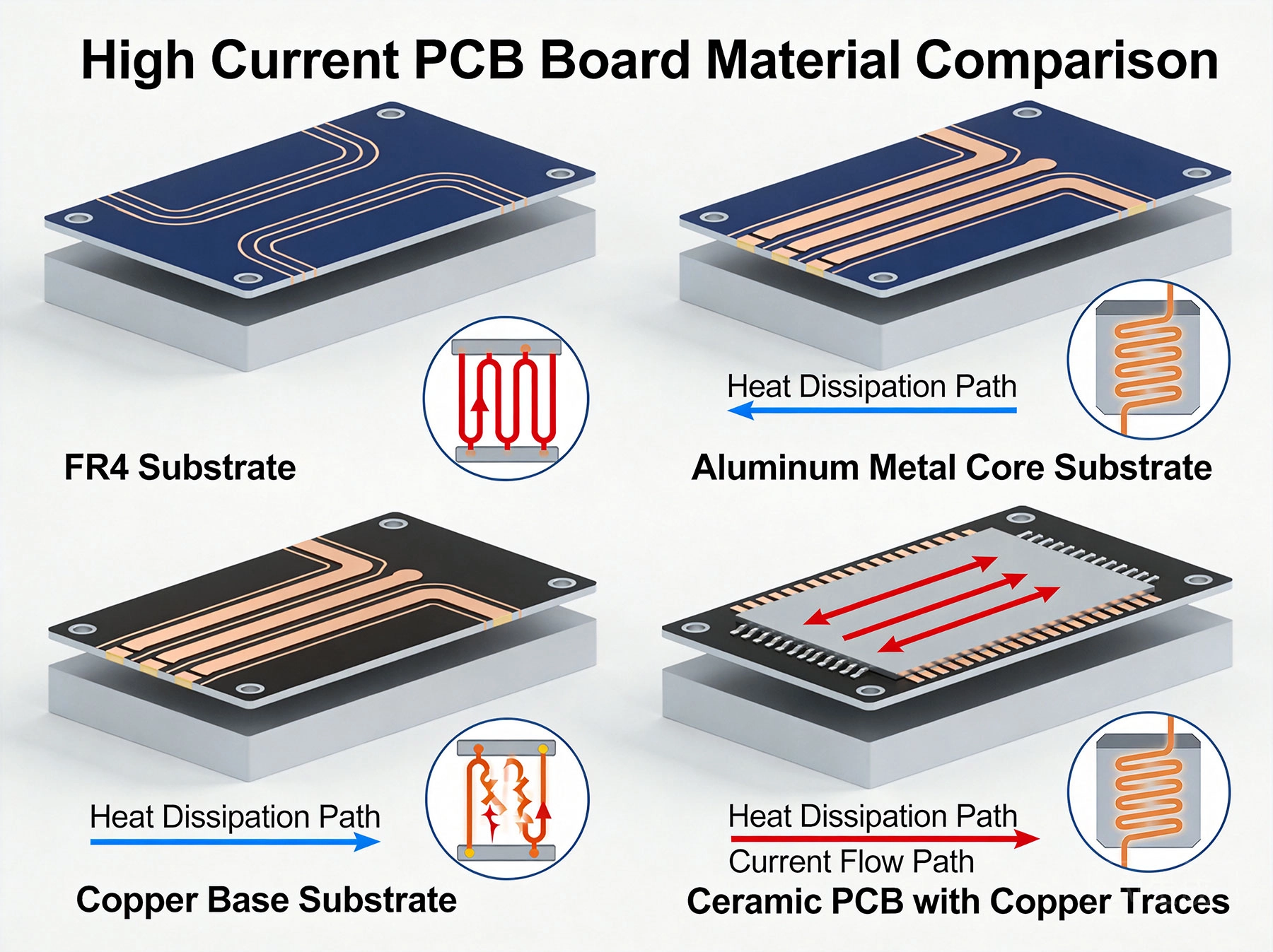
Standard FR-4 (Flame Retardant 4) is the most common PCB substrate—found in everything from smartphones to computers. For high current applications, upgraded versions with higher Tg values offer better thermal performance.
What it is: Epoxy resin reinforced with woven glass fiber. The "FR-4" designation indicates flame-retardant compliance with UL94 standards.
Thermal properties: Standard FR-4 has Tg around 130-140°C and thermal conductivity of 0.25-0.35 W/m·K. High-Tg variants (Tg 150-170°C) provide better thermal stability for power applications.
When to use it: Applications requiring moderate current (up to 10-15A) with standard Thermal Management. Suitable for power supplies, motor controllers, and battery management systems where heat can be dissipated through external heatsinks and airflow.
Advantages: Low cost, excellent manufacturing infrastructure, wide availability, good mechanical properties, compatible with standard assembly processes.
Limitations: Poor natural thermal conductivity, limited copper thickness options, not ideal for extremely high current or high ambient temperature environments.
Metal core PCBs replace the standard FR-4 core with a metal base—typically aluminum, though copper and brass options exist. This dramatically improves heat spreading and dissipation.
What it is: A PCB construction where the core material is aluminum (most common), copper, or an aluminum alloy, with dielectric insulation layer and copper circuitry bonded on top.
Thermal properties: Aluminum thermal conductivity ranges from 1-2 W/m·K (with dielectric) to over 200 W/m·K for direct bonded copper (DBC) substrates. This enables heat to spread across the entire board surface rather than localizing near components.
When to use it: LED lighting (where it originated), power converters, motor drives, automotive electronics, and any application where heat dissipation is critical. Ideal for 20A+ current applications where thermal management is the primary constraint.
Advantages: Excellent thermal conductivity, heat spreading across large areas, can be attached directly to heatsinks or enclosures, reduces need for Thermal Vias and external heatsinks.
Limitations: More expensive than FR-4, heavier (especially copper variants), limited layer count (typically single or double sided), specialized manufacturing required, cannot be machined after production.
IMS PCBs are a specific type of metal core PCB optimized for electrical isolation while maintaining thermal performance. The dielectric layer provides high thermal conductivity with electrical insulation.
What it is: Aluminum base with a thin, high-thermal-conductivity dielectric layer, topped with copper circuitry. The dielectric provides electrical isolation while allowing heat transfer.
Thermal properties: Thermal conductivity typically 1-5 W/m·K depending on dielectric thickness and material. The dielectric layer is the thermal bottleneck, so thinner is better for heat transfer but provides less isolation.
When to use it: Applications requiring electrical isolation from the metal base while needing superior thermal performance. Common in automotive LED modules, motor controllers, and power modules where the PCB mounts directly to a grounded metal chassis.
Advantages: Good thermal performance combined with electrical isolation, can mount directly to grounded surfaces, widely available from multiple manufacturers, good balance of cost and performance.
Limitations: More expensive than FR-4, dielectric properties can affect high-frequency performance, typically limited to 1-2 layers.
For the most demanding high current and high temperature applications, ceramic substrates offer unmatched thermal performance and reliability. These are premium materials found in aerospace, military, and industrial power electronics.
What it is: Substrates made from ceramic materials—typically aluminum oxide (Al2O3), aluminum nitride (AlN), or silicon carbide (SiC)—with direct bonded copper or thick film conductors.
Thermal properties: Exceptional thermal conductivity—Al2O3 at 20-30 W/m·K, AlN at 150-180 W/m·K. Some DBC substrates achieve thermal conductivity over 400 W/m·K. Additionally, ceramics can operate at temperatures exceeding 500°C, far beyond any polymer-based material.
When to use it: Military/aerospace power electronics, high-power inverters, IGBT modules, traction drives, and applications where reliability cannot be compromised. Also used in RF and microwave power amplifiers where low loss tangent matters.
Advantages: Highest thermal conductivity available, excellent high-temperature capability, good dielectric properties, matched thermal expansion with silicon, can handle extreme current densities.
Limitations: Significantly higher cost, brittle (can crack under mechanical shock), requires specialized assembly processes, limited availability compared to FR-4 or MCPCB.
Between standard FR-4 and ceramics, advanced laminates offer improved thermal and electrical properties for demanding applications without ceramic's cost and fragility.
What it is: Specialty substrates using advanced resin systems (polyimide, PTFE, cyanate ester) with high-performance reinforcement (low-loss glass, aramid, quartz). Examples include Rogers RT/duroid, Isola I-Speed, and Panasonic Megtron.
Thermal properties: Vary widely by material system. Polyimide offers Tg above 250°C with moderate thermal conductivity. PTFE-based materials (RT/duroid) excel in high-frequency applications with low loss tangent. Thermal conductivity typically 0.3-0.5 W/m·K, lower than MCPCB but with superior high-temperature capability.
When to use it: High-reliability aerospace and defense electronics, high-frequency power applications (SiC and GaN inverters), applications requiring high temperature operation or low signal loss, multilayer boards with complex thermal requirements.
Advantages: Excellent thermal resistance (high Tg and Td), good electrical properties, compatible with multilayer constructions, available in high-layer-count formats, better mechanical toughness than ceramics.
Limitations: More expensive than standard FR-4, some materials require specialized processing, not as thermally conductive as metal core options.
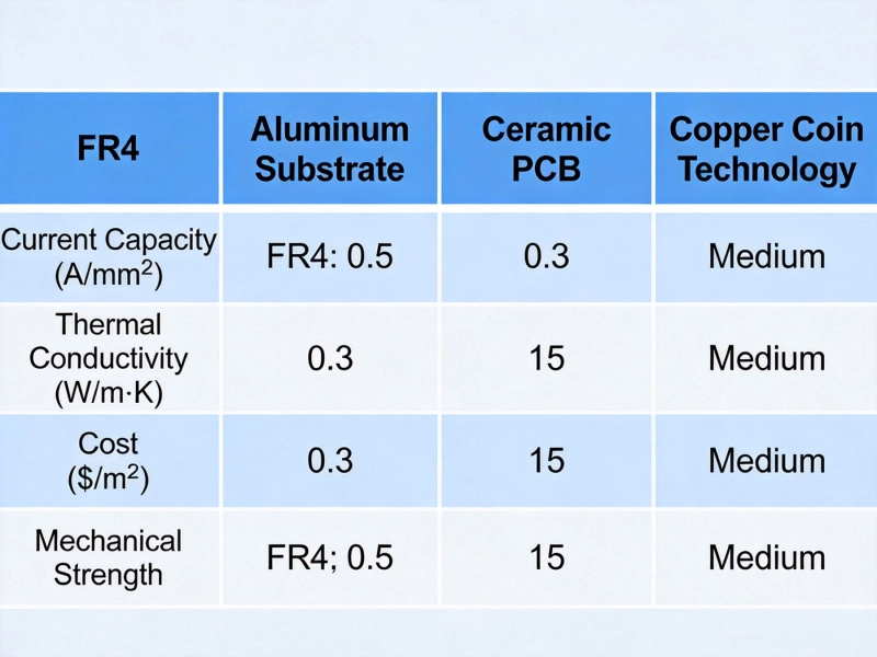
Here's a quick reference comparing these material options across key parameters:
Thermal Conductivity (W/m·K):
Maximum Operating Temperature (°C):
Relative Cost Index:
Standard 1oz FR-4 works well for most low-current applications. Focus on proper trace width calculations using IPC standards, and ensure adequate clearance for voltage isolation. Thermal management is rarely a primary concern.
Material recommendation: Standard FR-4 (Tg 130-140°C)
Consider upgrading to 2oz copper and using wider traces or copper pours. High-Tg FR-4 provides thermal margin for components that generate heat. Use Thermal Vias to spread heat to internal planes or back-side copper.
Material recommendation: High-Tg FR-4 with 2oz copper
Metal core or IMS PCBs become attractive here. Heavy copper (3-4oz) on FR-4 works for some applications, but thermal management requires attention. Consider direct mounting to heatsinks, thermal vias, and forced air cooling. Bus bars may supplement PCB traces for very high currents.
Material recommendation: IMS/MCPCB or High-Tg FR-4 with 3-4oz copper and thermal vias
Metal core PCBs are typically necessary for continuous high-current operation. For extreme applications (100A+), consider embedded copper bus bars, direct bonded copper substrates, or even bus bars separate from the PCB entirely. Thermal design becomes the primary constraint.
Material recommendation: MCPCB with direct thermal path to heatsink, or ceramic/DBC for mission-critical applications
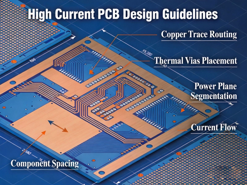
Material choice is only part of the solution. Effective thermal management combines material properties with design techniques:
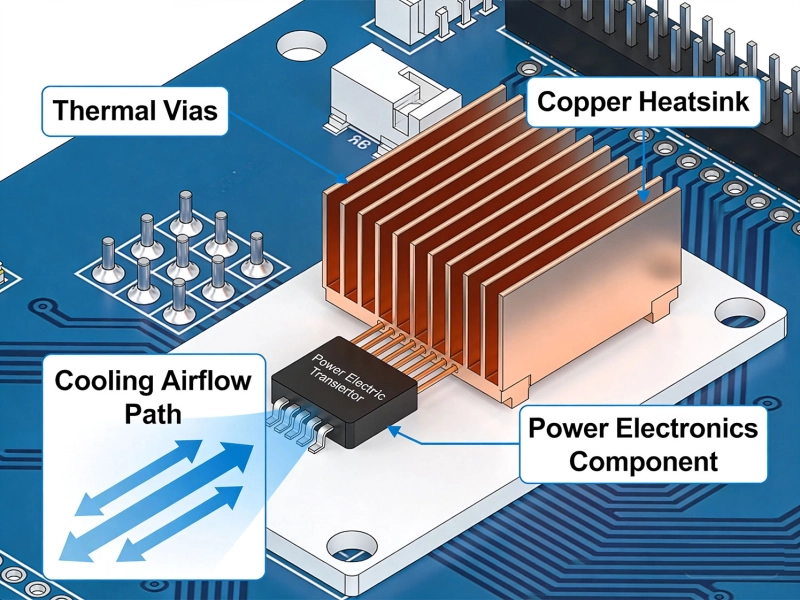
Thermal vias: Place thermal vias under heat-generating components to conduct heat to other layers or the board backplane. Use filled or plated-through vias for better thermal conductivity. Typical thermal via arrays: 0.3-0.5mm diameter, 1-1.5mm pitch.
Copper pours: Spread heat across large copper areas. Connect thermal vias between top and bottom pours for best results. Ensure pours have thermal relief connections to pads to avoid assembly issues.
Component placement: Position heat-sensitive components away from heat sources. Consider airflow patterns when arranging components—let convection work for you.
Heatsinks: Attach heatsinks to components and PCB areas carrying high current. Thermal interface materials (TIM) between the PCB and heatsink ensure good thermal coupling.
Active cooling: For extreme power densities, fans or liquid cooling may be necessary regardless of substrate material. Plan mounting points and thermal paths during initial design.
Design for manufacturing to avoid costly surprises:
Heavy copper PCBs: Thicker copper requires longer etching times and may affect fine feature tolerances. Discuss capabilities with your manufacturer early. Standard FR-4 suppliers may cap at 2-3oz, while specialized facilities handle 5-10oz.
Metal core PCBs: Only certain manufacturers produce MCPCBs. Lead times are typically longer than standard FR-4. Panel sizes may be different—many MCPCB shops use different standard formats.
Ceramic substrates: Require specialized handling and assembly. Soldering profiles differ from FR-4, and some processes (like reflow) may need adjustment. Work closely with your manufacturer on assembly guidelines.
Material availability: Some specialty materials have long lead times or limited distributors. Check availability before committing to a specific material for production.
When selecting your High Current Pcb material, consider these factors in order of importance for your application:
Thermal requirements: How much heat needs to be dissipated? What's the maximum operating temperature? Is natural convection sufficient or is active cooling required?
Current and voltage: What current levels must traces carry? What isolation voltages are required? Do you need multi-layer construction?
Environmental conditions: Will the board operate in high ambient temperatures? Are temperature cycles expected? Is the application safety-critical?
Mechanical requirements: Are there weight constraints? Will the board experience vibration or shock? Is the board size constrained?
Cost targets: What's the budget per board? What's the expected production volume? Can you amortize tooling costs over larger runs?
Choosing the best material for High Current Pcb Design requires balancing thermal performance, electrical requirements, manufacturing constraints, and cost. For most applications, high-Tg FR-4 with appropriately thick copper provides adequate performance at reasonable cost. When thermal management becomes critical, metal core (IMS) PCBs offer an excellent middle ground between standard FR-4 and premium ceramic substrates.
Start with your Thermal Analysis—determine how much heat must be dissipated and where it originates. This drives material selection more than any other factor. From there, consider your current density requirements, operating environment, and production volume to narrow the options.
Remember that material selection isn't isolated from other design decisions. Trace geometry, via design, component placement, and cooling strategies all interact with your substrate choice. The best results come from treating thermal management as a system-level challenge rather than selecting a "hot" material and hoping it works.
When in doubt, consult with your PCB manufacturer early in the design process. Their experience with material performance in production can save costly redesigns and ensure your boards perform reliably in the field.
High Current PCB Design GuidelinesMay/21/2026
IPC-2152 Current Carrying Capacity: The Definitive PCB Trace Calculator GuideMay/21/2026
Heavy Copper vs Standard Copper PCB: Complete Comparison Guide for EngineersMay/20/2026
Plated Through Hole Current Rating: Complete Guide for PCB DesignersMay/21/2026
Mastering IPC-2152 Current Carrying Capacity Calculation for Reliable PCB DesignJune/04/2026
How Much Current Can a PCB Trace Carry? Complete Engineering GuideMay/20/2026
Best Material for High Current PCB DesignMay/21/2026
Why Your High-Power PCBs Overheat (And the 5 Methods That Actually Fix It)May/20/2026