

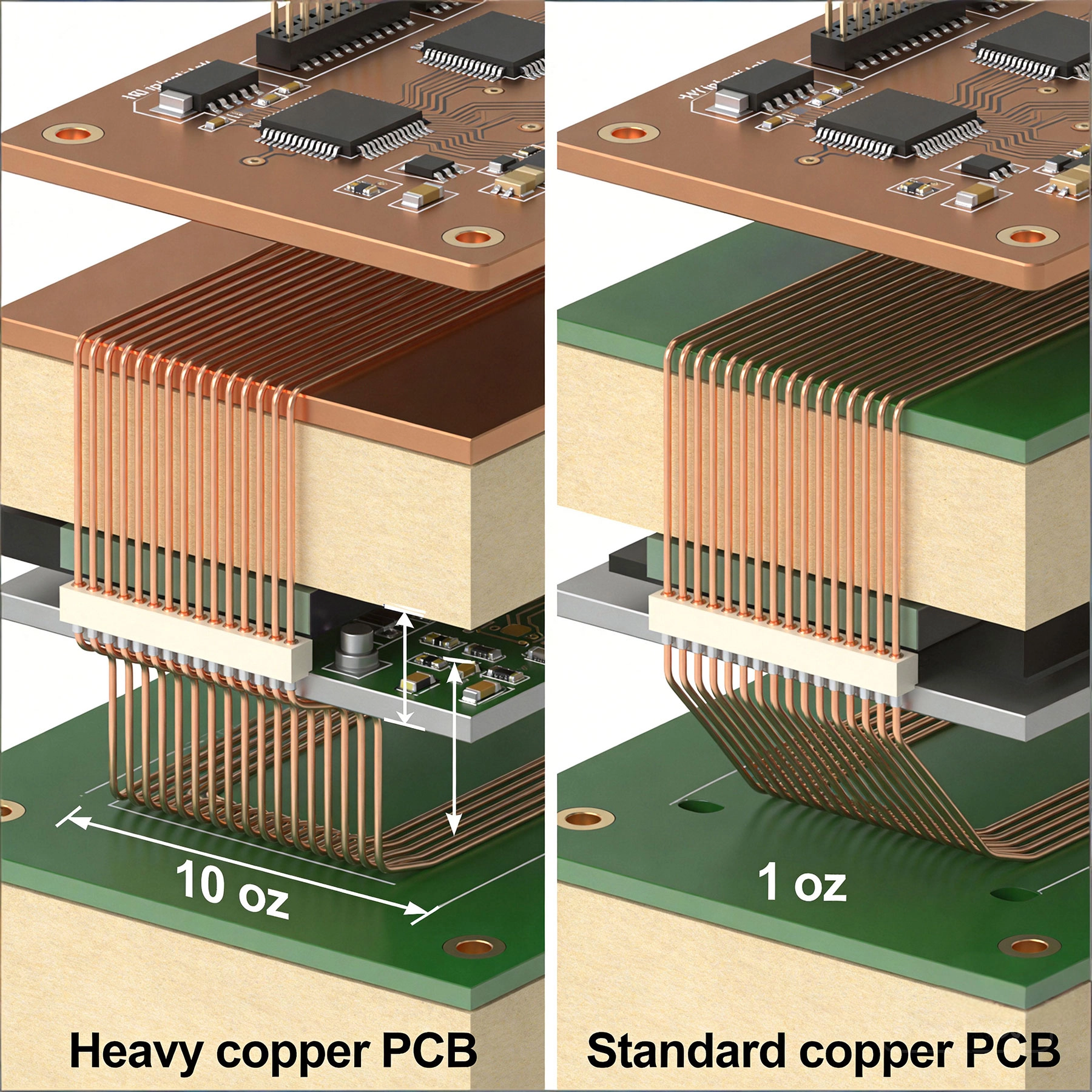
Heavy copper PCBs offer significantly more copper thickness for high-power applications compared to standard PCBs Introduction: Understanding Copper Weight in PCB Design When designing printed circuit boards, one of the most critical decisio...
https://www.high-current-pcb.com/high-current-pcb-manufacturing-tech/heavy-copper-vs-standard-copper-pcb-complete-comparison-guide-for-engineers/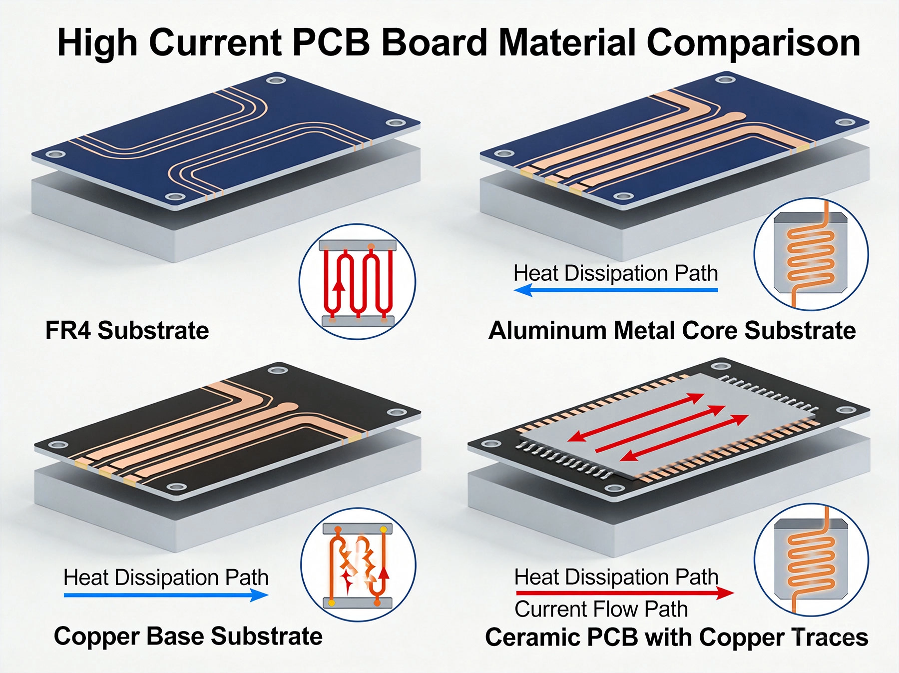
Power electronics are everywhere—from electric vehicle charging stations to industrial motor drives, from solar inverters to server power supplies in data centers. These systems transmit large currents, and heat is generated when current flows thro...
https://www.high-current-pcb.com/high-current-pcb-materials-standards/best-material-for-high-current-pcb-design-how-to-choose-the-right-substrate/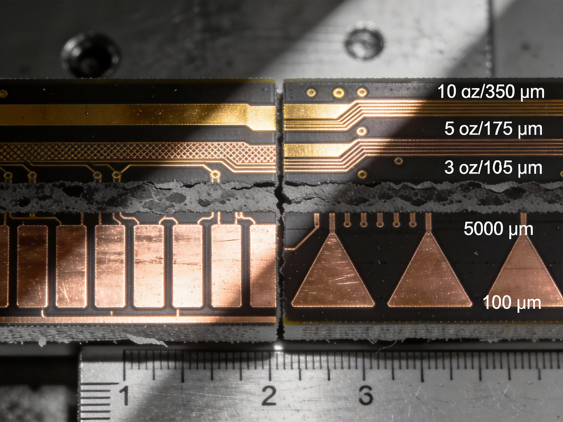
Copper weight selection stands among the most consequential decisions in power electronics PCB design. The choice between 2oz and 4oz copper affects everything from current-carrying capacity and thermal performance to manufacturing cost and fabrica...
https://www.high-current-pcb.com/automotive-ev-systems/cost-comparison-2oz-vs-4oz-copper-pcb-what-you-need-to-know/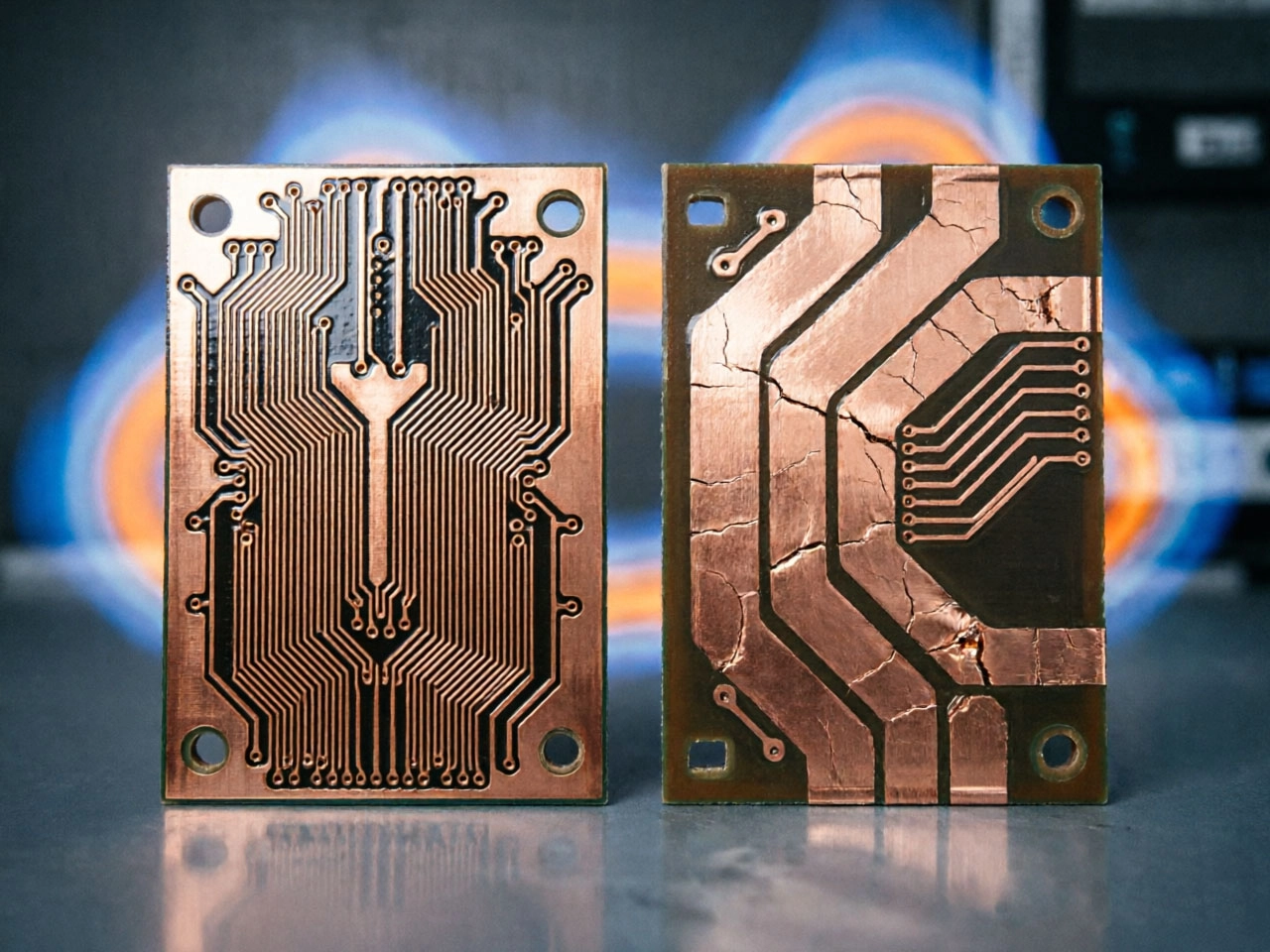
Every PCB generates heat when current flows through its traces. At low current levels—tens or hundreds of milliamps—the heat is negligible, dissipated quickly by the surrounding material, and rarely a concern. But when current climbs into the amper...
https://www.high-current-pcb.com/high-current-pcb-manufacturing-tech/high-current-pcb-vs-standard-pcb-a-real-world-thermal-stress-test/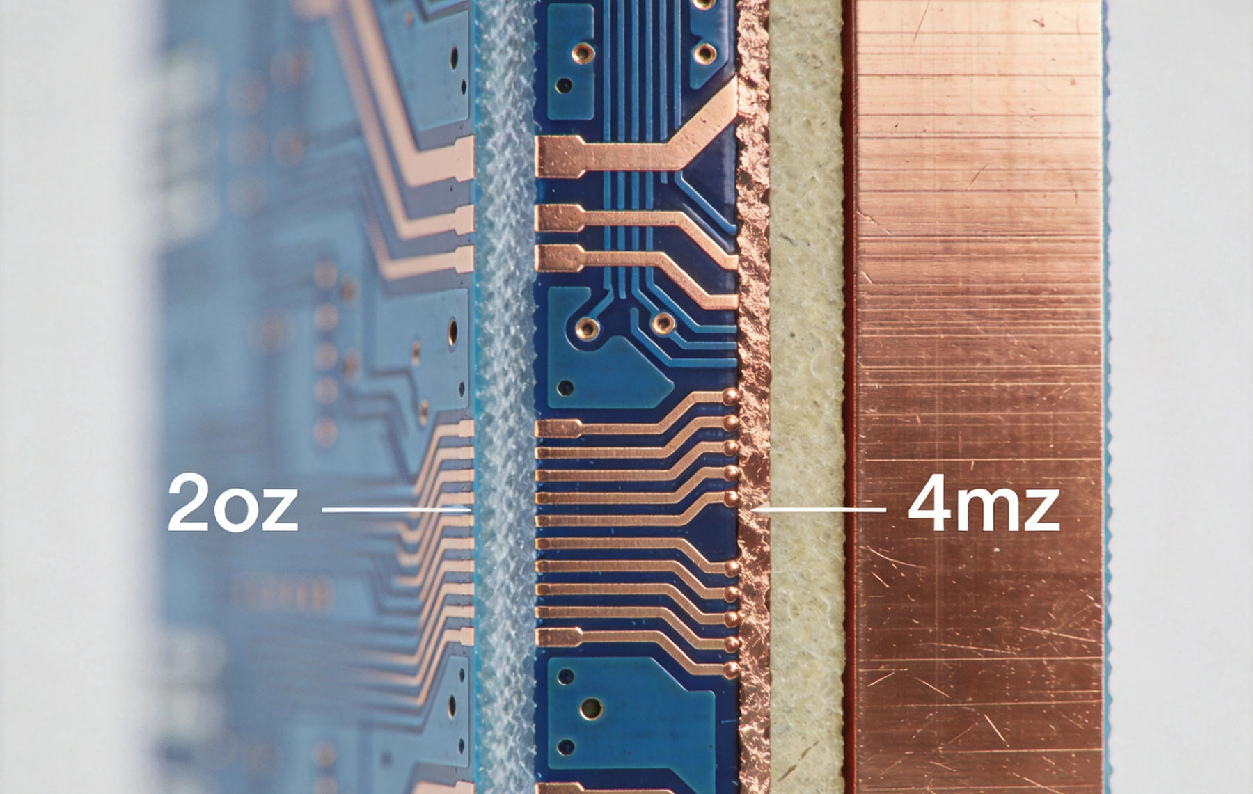
When designing printed circuit boards for high current applications, copper thickness becomes a critical decision that impacts everything from electrical performance to thermal management and manufacturing cost. The choice between 2oz and 4oz coppe...
https://www.high-current-pcb.com/high-current-pcb-thermal-design/2oz-vs-4oz-copper-which-is-best-for-your-high-current-pcb/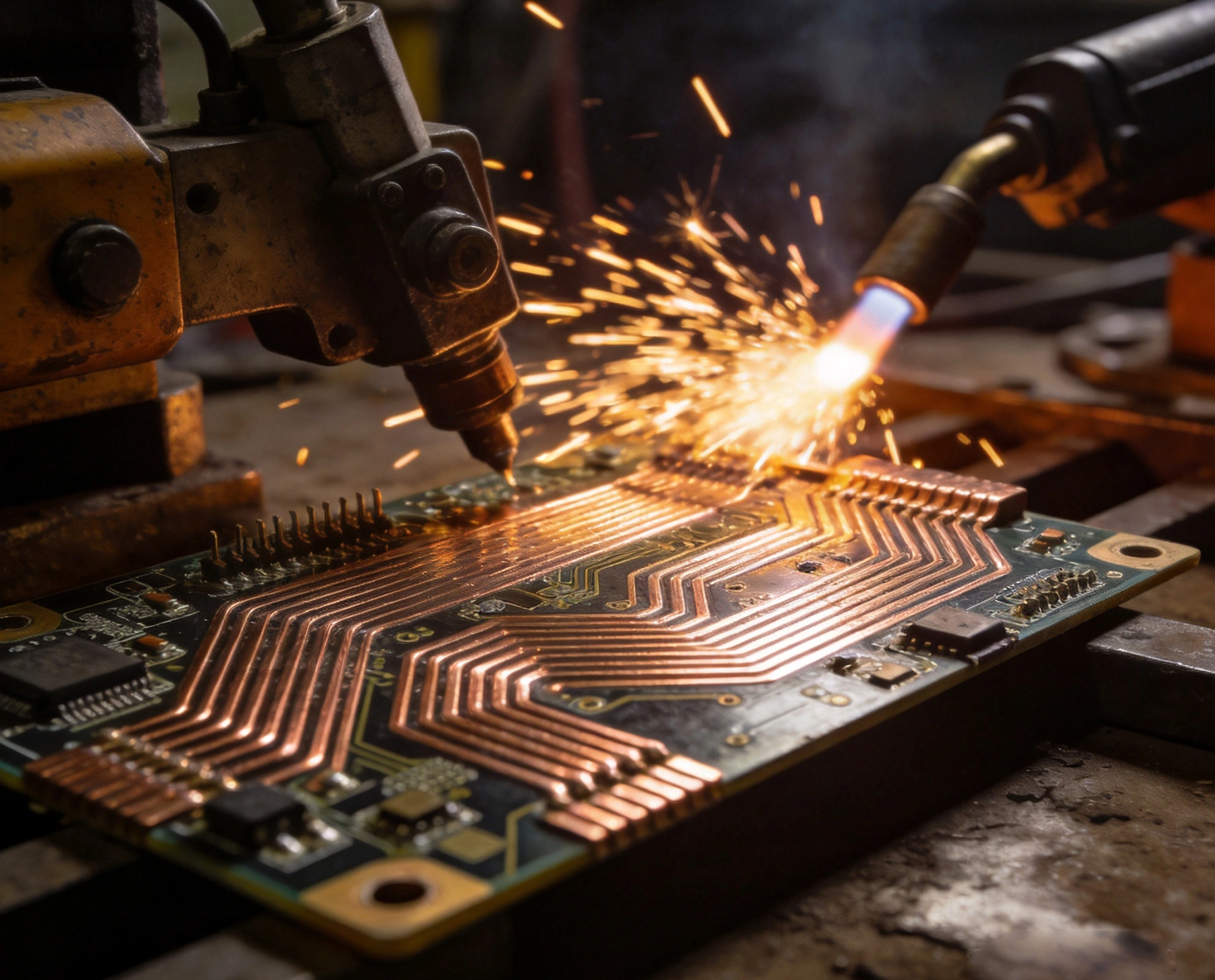
Industrial welding equipment pushes the boundaries of what a printed circuit board is expected to do. Unlike consumer electronics, where currents are measured in milliamps and thermal margins are generous, welding machines demand PCB designs that c...
https://www.high-current-pcb.com/high-current-pcb-thermal-design/designing-a-high-current-pcb-for-industrial-welding-equipment/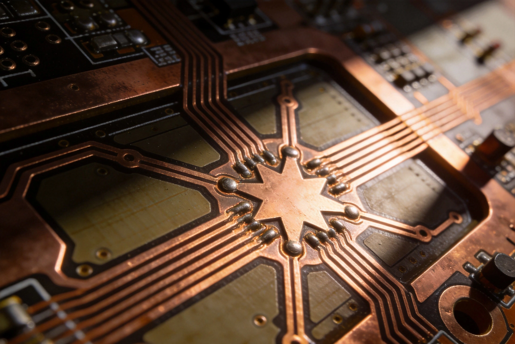
Grounding strategy represents one of the most critical decisions in high current PCB design. Whether you are building a motor drive, power supply, or battery management system, the way you handle ground connections directly impacts performance, eff...
https://www.high-current-pcb.com/telecom-5g-high-speed-computing/high-current-pcb-grounding-star-ground-vs-ground-plane-in-high-current-paths/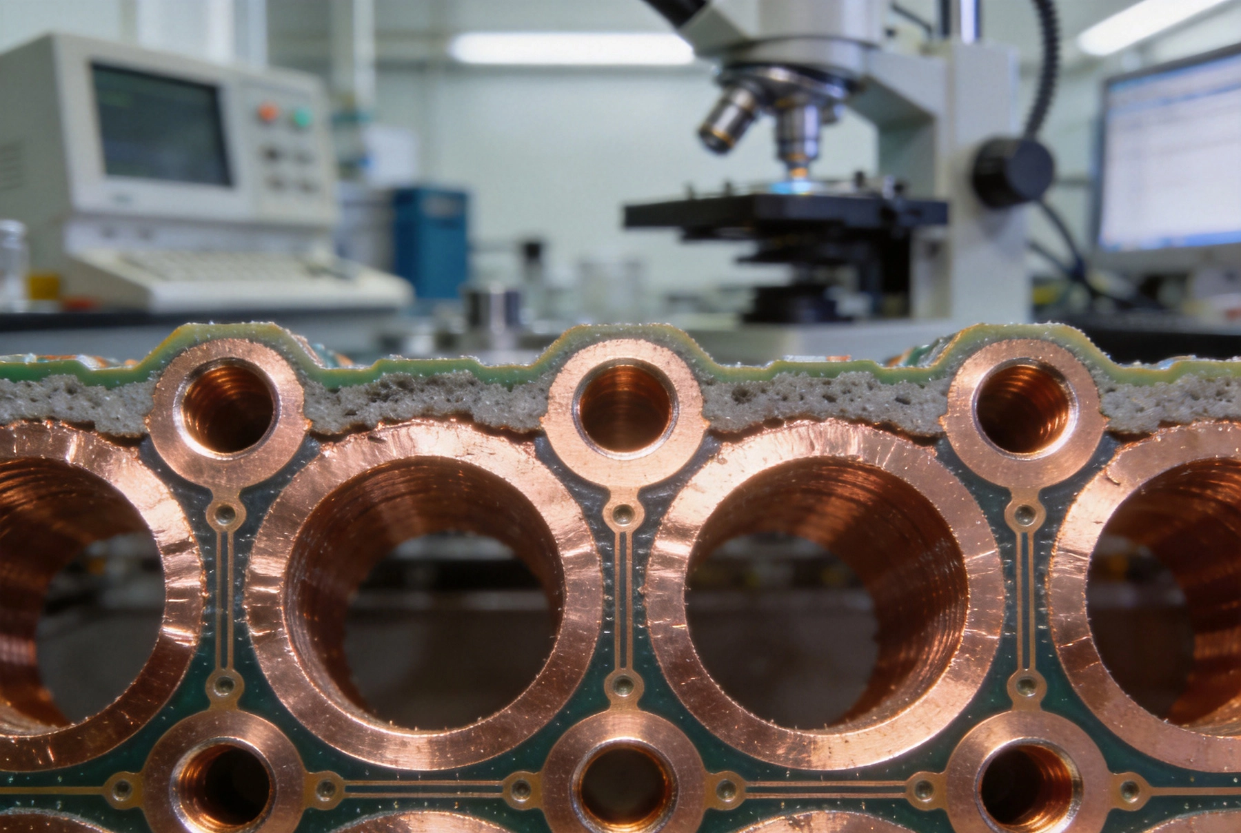
Via plating thickness represents one of the most consequential specifications in high current PCB design. When engineers design power distribution networks for automotive motor drives, industrial motor controllers, or server power supplies, the cop...
https://www.high-current-pcb.com/high-current-pcb-dfm-tips/high-current-pcb-via-plating-1mil-vs-2mil-thickness-reliability-test/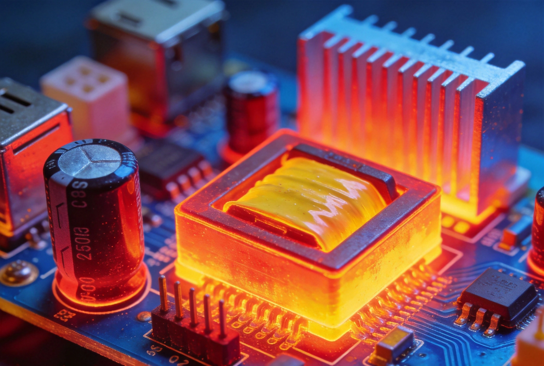
High-frequency switching regulators power everything from server motherboards to automotive electronics. At frequencies above 500 kHz—and increasingly pushing past 1 MHz—these power conversion circuits demand PCB layouts that would make an aerospac...
https://www.high-current-pcb.com/high-current-pcb-thermal-design/high-current-pcb-design-for-high-frequency-switching-regulators/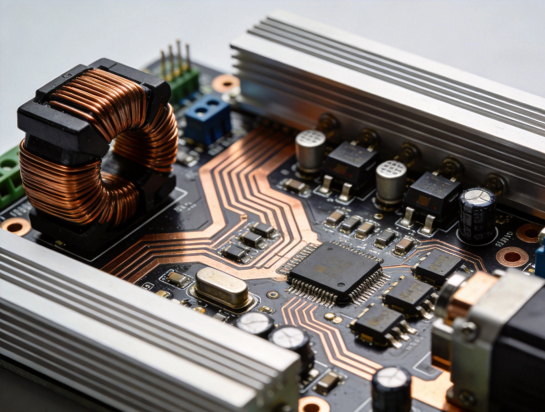
Robotics motor controllers operate in one of the most demanding environments in power electronics. These systems must deliver high currents with precision timing, manage thermal loads from tens to hundreds of watts, and maintain reliability despite...
https://www.high-current-pcb.com/high-current-pcb-thermal-design/high-current-pcb-design-for-robotics-motor-controllers/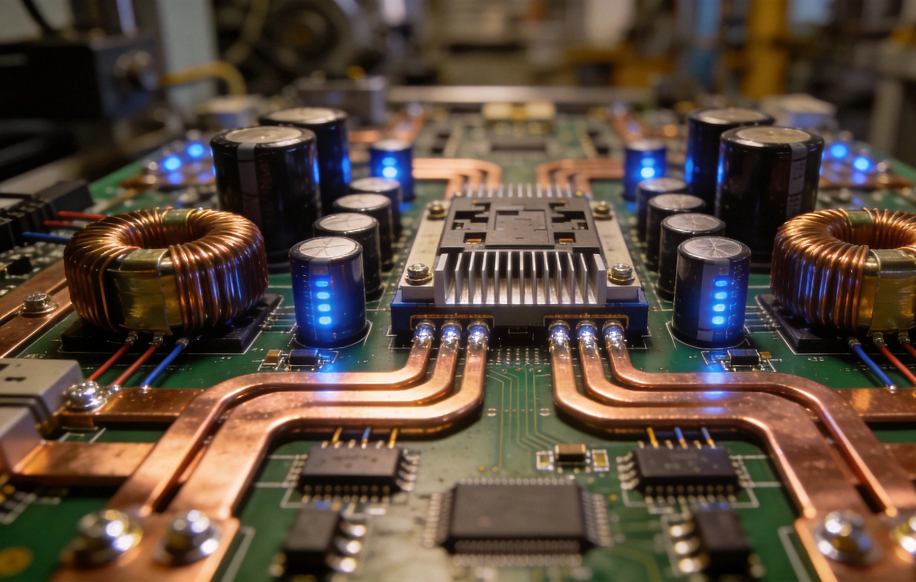
Industrial motor drives are among the most demanding applications in power electronics. A variable frequency drive (VFD) controlling a 30kW motor might switch hundreds of amps at bus voltages of 400V to 690V, generating heat inIGBT modules, DC link...
https://www.high-current-pcb.com/high-current-pcb-thermal-design/high-current-pcb-design-for-industrial-motor-drives/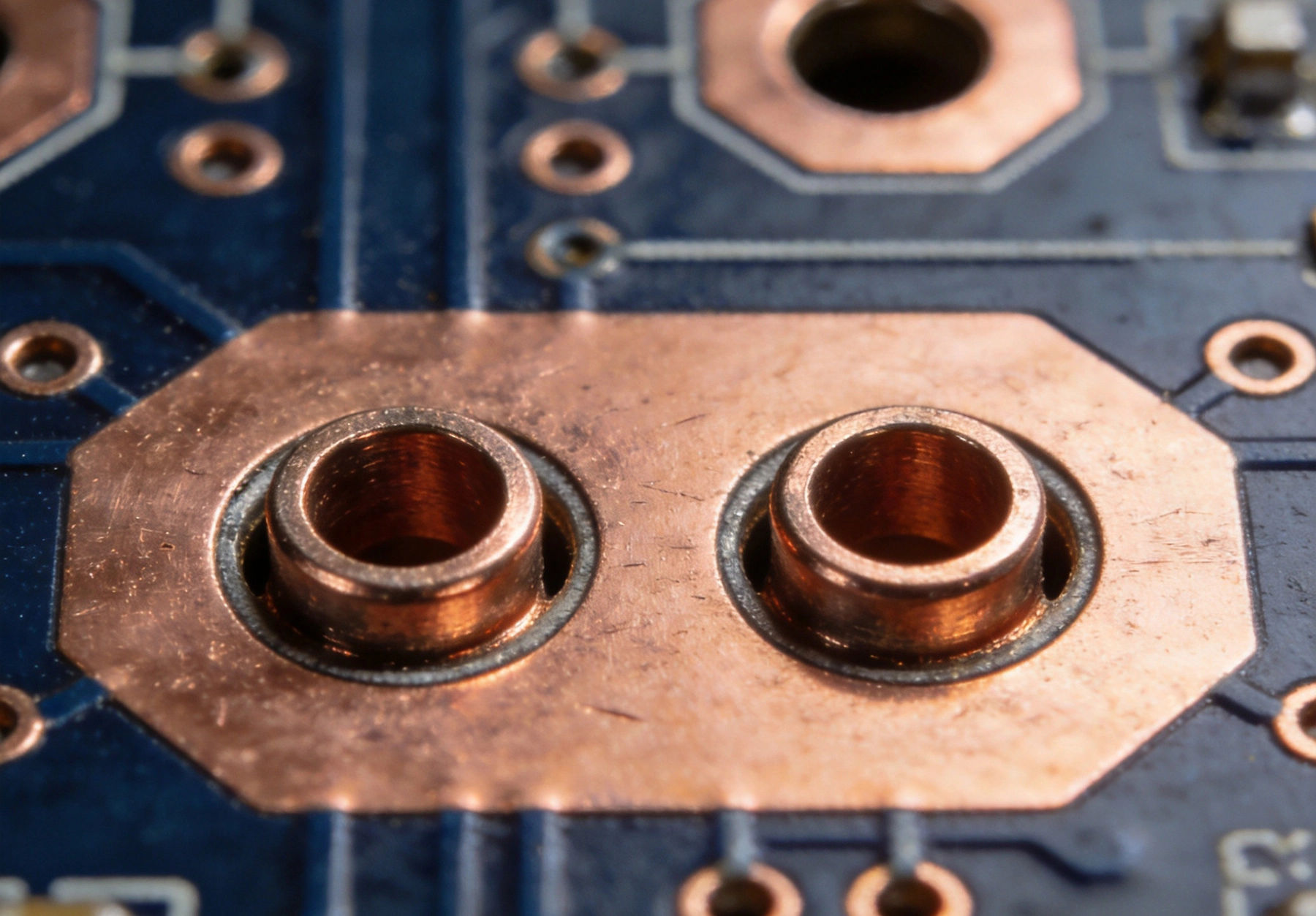
Mounting holes on printed circuit boards serve a dual purpose that many designers overlook: they secure the board to its chassis or enclosure, and when properly designed, they can also serve as critical current return paths between the PCB ground p...
https://www.high-current-pcb.com/automotive-ev-systems/high-current-pcb-mounting-holes-plated-vs-non-plated-for-current-return/