
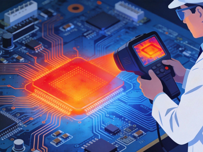
In the world of Printed Circuit Board (PCB) design, Thermal Management is often the silent killer of reliability. While signal integrity and component placement get a lot of attention, ensuring your copper traces can handle the required current without melting or causing excessive voltage drop is fundamental. For decades, designers relied on older nomographs, but today, the gold standard is the Ipc-2152 Standard.
This article explores how to perform an accurate Ipc-2152 Current Carrying Capacity calculation and why moving away from legacy methods like Ipc-2221 is crucial for modern electronics.
Before 2009, most engineers used Ipc-2221 (and its predecessor IPC-D-275) to determine trace width. These standards provided generic curves based on limited testing from the mid-20th century. They tended to be overly conservative for external layers and dangerously optimistic for internal layers because they didn't account for the specific thermal environment of the board.
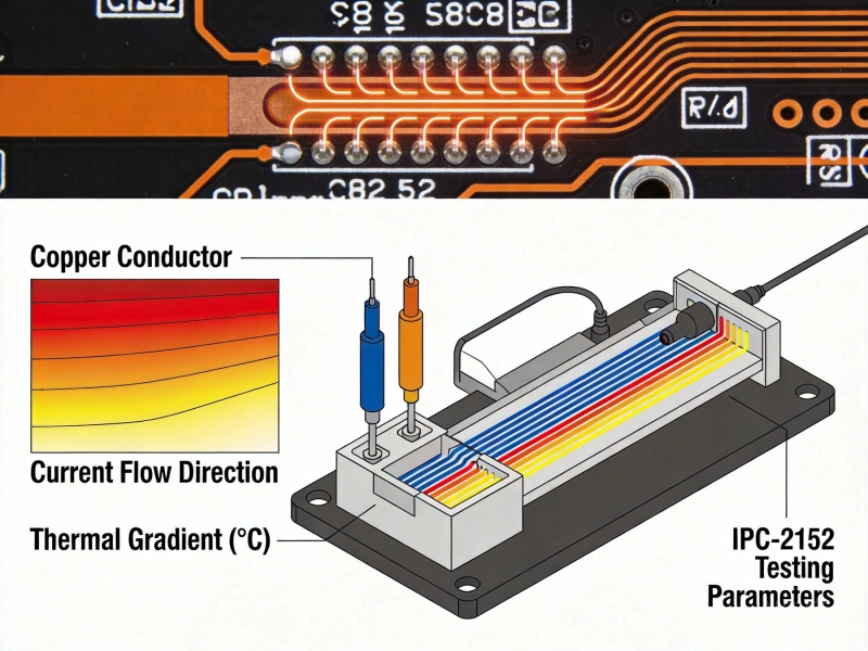
IPC-2152, titled "Standard for Determining Current-Carrying Capacity in Printed Board Design," changed the game. It is based on extensive empirical testing involving over 300 test boards. It accounts for variables that previous standards ignored, such as:
When performing an IPC-2152 Current Carrying Capacity calculation, you are essentially solving for one variable (usually Trace Width) based on three critical inputs:
One of the most significant improvements in IPC-2152 is the distinction between layer types:
While the full IPC-2152 standard involves complex mathematical modeling and look-up charts, most engineers utilize software tools or simplified equations derived from the standard data.
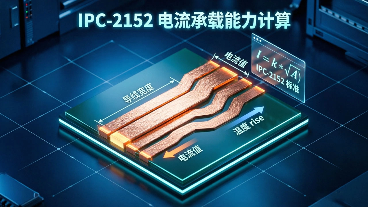
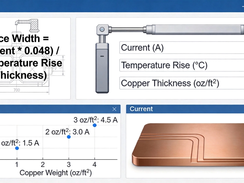
A common simplified approach derived from the IPC-2152 data curves uses the following logic:
Area (mils²) = (Current / (k * TempRise^b))^(1/c)Width (mils) = Area / (Thickness (oz) * 1.37)
Note: The constants k, b, and c differ for internal and external layers.
However, for high-reliability designs, it is highly recommended to use dedicated Pcb Design software (like Altium, Cadence, or Siemens Xpedition) or online calculators specifically certified to IPC-2152, as they factor in the cross-sectional area and plane proximity more accurately than simple formulas.
To ensure your IPC-2152 current carrying capacity calculation results in a robust design, keep these tips in mind:
Adopting IPC-2152 for your current carrying capacity calculations is no longer optional for professional-grade electronics; it is a necessity. By understanding the interplay between Copper Weight, temperature rise, and board construction, you can optimize your trace widths—saving board space where possible and adding safety margins where necessary. Don't let your Pcb Design go up in smoke; trust the data, verify your calculations, and design with confidence.
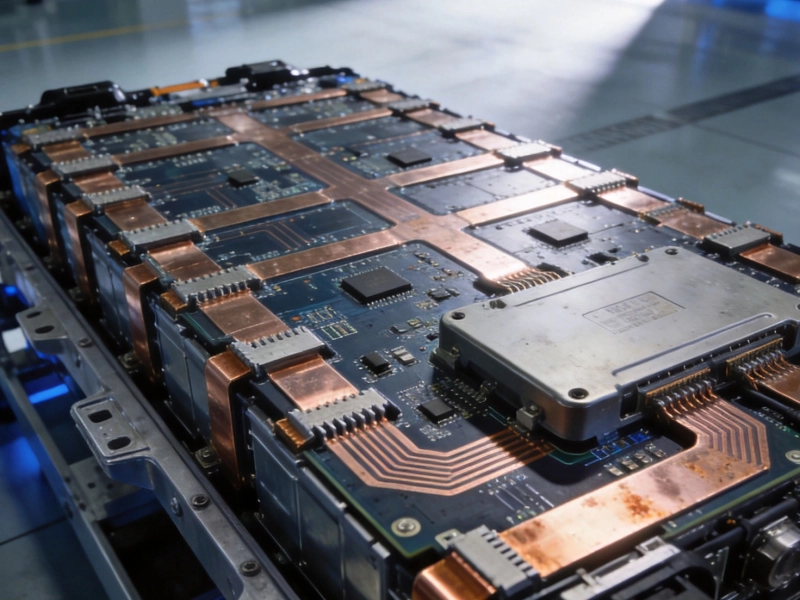
Designing a 100A High Current PCB for EV Battery Management SystemsJuly/09/2026
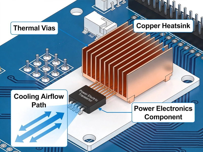
Why Your High-Power PCBs Overheat (And the 5 Methods That Actually Fix It)May/20/2026
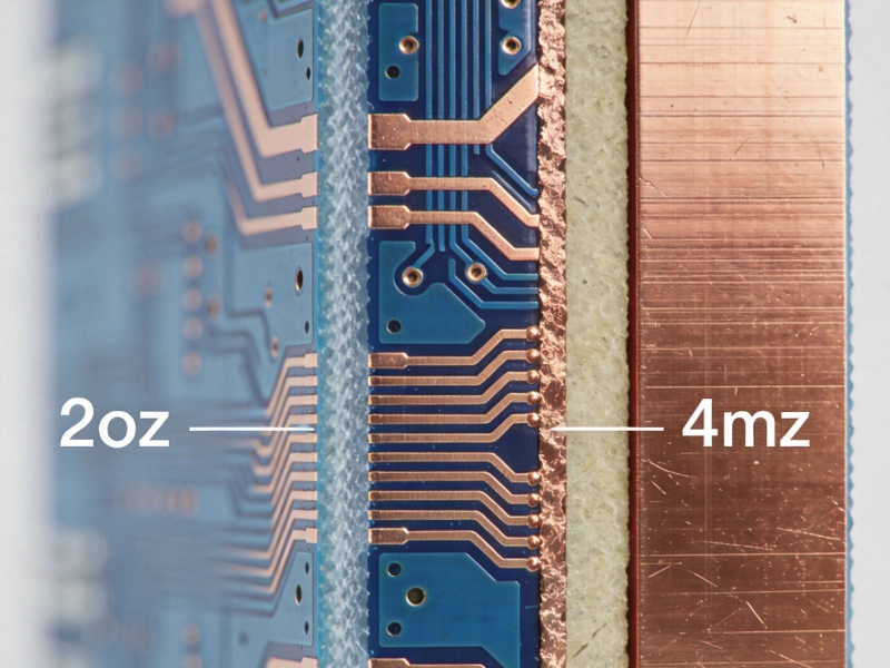
2oz vs. 4oz Copper: Which is Best for Your High Current PCB?July/10/2026
High Current PCB Trace Width Calculator: The Ultimate Engineering GuideMay/20/2026
5 Critical Thermal Management Problems in High Power PCBsMay/21/2026
IPC-2152 Current Carrying Capacity Calculation GuideJune/03/2026

High Current PCB Thermal Relief: Full Connect vs. Modified SpokesJuly/16/2026
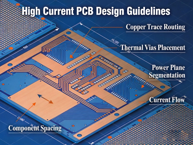
High Current PCB Design GuidelinesMay/21/2026