
Electrical connections form the backbone of every electronic system, and when your projects involve significant power delivery, the stakes rise considerably. A poorly selected High Current Pcb connector can undermine even the most carefully designed power circuitry, leading to excessive voltage drops, dangerous overheating, intermittent operation, or complete system failure. Yet despite this critical importance, connector selection often receives far less engineering attention than the active circuitry it serves.
This comprehensive guide walks through everything you need to know about selecting High Current Pcb connectors that will reliably serve your Power Electronics projects. Whether you're designing battery management systems, motor drives, power supplies, or industrial control equipment, understanding connector specifications, thermal considerations, and application requirements will help you make informed decisions that ensure long-term reliability and safe operation.

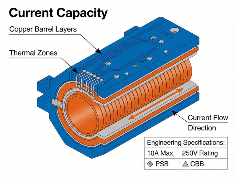
The most obvious specification for any High Current connector is its current rating. However, understanding what that rating means—and its practical limitations—requires deeper examination than simply matching numbers.
Manufacturer-specified current ratings typically represent values achieved under controlled laboratory conditions with specific wire gauges and ambient temperatures. Real-world applications rarely match these ideal circumstances. The actual usable current through a connector depends on multiple factors:
Professional engineers routinely derate connectors below their nominal specifications. A connector rated for 30 amperes might realistically handle 20-25 amperes continuously in a typical industrial enclosure environment. The exact derating factor depends on your specific thermal circumstances.
When current flows through any resistance, heat develops. Connectors with higher contact resistance generate more heat for the same current flow. Industry standards typically specify acceptable temperature rise limits:
When evaluating connectors, look for those that specify temperature rise data rather than simply stating current ratings. This information enables more accurate thermal modeling of your complete system.
While current rating captures most attention for power connectors, voltage rating deserves equally serious consideration. Higher voltages create different failure modes that can prove dangerous if overlooked.
Voltage differences between adjacent terminals or between terminals and grounded metal create stress on insulating materials. Two parameters govern safety:
Higher operating voltages require greater spacing to prevent arc tracking across insulating surfaces. Standards such as IEC 60950 for information technology equipment and IEC 60601 for medical devices specify minimum creepage and clearance distances based on working voltage and pollution degree.
Connector housings made from different materials provide varying levels of electrical isolation:
For high-voltage applications, ensure the connector's insulation material and construction satisfy relevant safety standards for your market and application.
The heart of any connector lies in its contact system. Contact design, material selection, and plating all influence performance, longevity, and compatibility.
Contact resistance represents the opposition to current flow at the mating interface. Lower resistance means less power loss and heat generation. Quality power connectors typically specify contact resistance below 1 milliohm, with premium designs achieving 0.2-0.5 milliohms.
Contact resistance increases over time due to factors including:
Base contact materials are typically brass or phosphor bronze, with plating applied to improve conductivity and corrosion resistance:
Larger contact surfaces distribute current flow more evenly and reduce current density. For high-current applications, look for:
High Current Pcb Connectors employ various mechanisms for securing wire terminations. Each approach offers distinct advantages for specific applications.
Screw terminals represent the most common approach for high current applications:
Spring clamp technology offers tool-free wire insertion with automatic spring compensation:
For permanent, high-reliability applications, press-fit or solder terminations provide robust solutions:
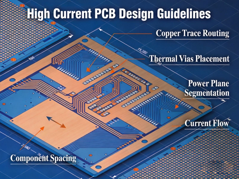
The connector itself is only part of the equation. Pcb Design significantly influences overall system performance and reliability.
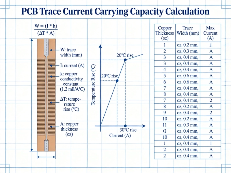
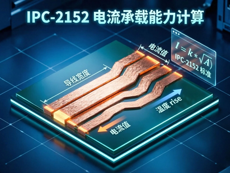
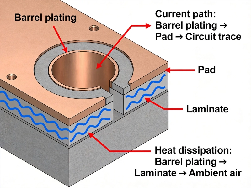
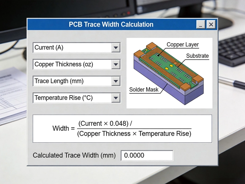
Current must flow through Pcb Traces to reach the connector. Standard 1 oz copper may prove inadequate for high-current paths:
Use PCB trace current calculators (such as those based on Ipc-2152 standards) to determine appropriate widths for your specific current, acceptable temperature rise, and Copper Thickness.
Heat spreading from connector termination areas requires Thermal Management:
High current connectors impose significant mechanical loads on PCB pads:
Different applications impose varying requirements that influence connector selection.
These applications typically require:
BMS applications demand:
Industrial motor applications require:
Third-party certifications provide assurance of connector quality and safety:
For applications in regulated industries (medical, automotive, aerospace), verify that connectors carry appropriate certifications for your specific market.
A connector rated for 30A at 25°C ambient may only safely carry 20A in a 60°C enclosure. Always evaluate connectors within your actual thermal context.
Using a connector rated for 250V in a 480V system creates dangerous safety margins. Match voltage ratings with appropriate derating factors for your system voltage.
A connector with excellent current rating means nothing if your wire gauge exceeds its termination capacity. Verify that connector terminals accept your required wire sizes.
Connections that seem permanent may require servicing. Consider whether field replacement will be necessary and select connectors that facilitate maintenance.
Proper installation ensures connectors perform to their specifications:
Before deployment, verify connector performance in your system:
High current PCB connector selection demands attention to electrical specifications, Thermal Management, mechanical robustness, and application requirements. By understanding how current ratings relate to real-world conditions, accounting for thermal factors in your design, and matching connector characteristics to your specific application needs, you can achieve reliable power connections that serve your systems throughout their intended lifetimes.
The stakes for proper connector selection extend beyond mere functionality. Inadequate connectors create safety hazards through overheating and potential fire risks. Taking time to evaluate options thoroughly, using appropriate derating factors, and following installation best practices protects both equipment and personnel while ensuring your Power Electronics projects deliver their intended performance reliably.
IPC-2152 Current Carrying Capacity: The Definitive PCB Trace Calculator GuideMay/21/2026
Best Material for High Current PCB Design: How to Choose the Right SubstrateJune/05/2026
High Current PCB Design GuidelinesMay/21/2026
High Current PCB Design Guidelines: Ensuring Reliability and SafetyJune/08/2026
Plated Through Hole Current Rating: Complete Guide for PCB DesignersMay/21/2026
Mastering IPC-2152 Current Carrying Capacity Calculation for Reliable PCB DesignJune/04/2026
Plated Through Hole Current Rating for PCBsJune/10/2026
High Current PCB Trace Width Calculator: Complete Guide with Formulas and ExamplesMay/20/2026