

When designing printed circuit boards for High Current applications, Copper Thickness becomes a critical decision that impacts everything from electrical performance to Thermal Management and Manufacturing Cost. The choice between 2oz and 4oz Copper Thickness can determine whether your Power Electronics operate reliably or overheat, whether your traces handle the required current without excessive voltage drop, and whether your product succeeds in demanding applications. This comprehensive guide examines both copper weights, their capabilities, limitations, and optimal applications to help you make the right choice for your High Current PCB design.
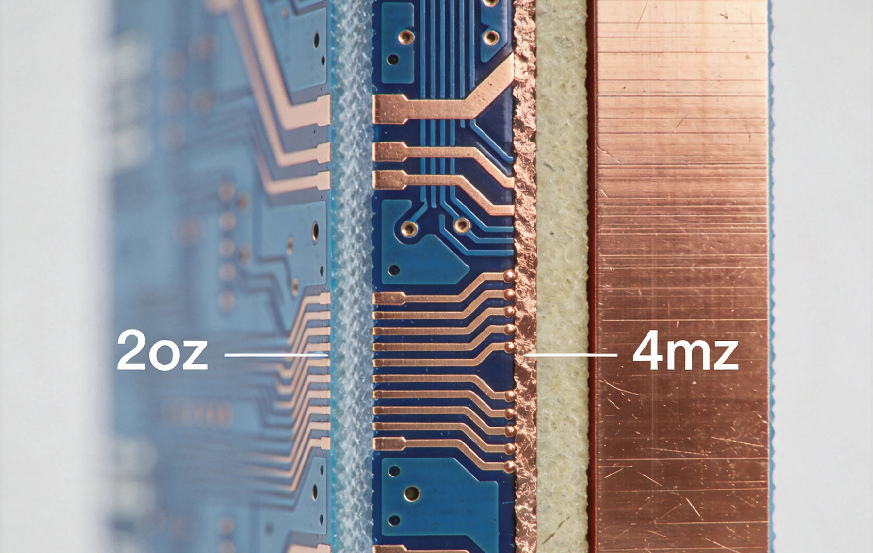
Before diving into the comparison, it's essential to understand what Copper Weight means in PCB terminology. Copper Weight, measured in ounces per square foot (oz/ft²), indicates the thickness of the copper layer on a PCB. This measurement originated from the weight of copper foil required to cover one square foot of surface area.
The relationship between copper weight and actual thickness is standardized in the PCB industry. One ounce of copper per square foot equals approximately 1.37 mils (0.0347 mm or 34.7 micrometers) in thickness. After plating and finishing processes, the final thickness may vary slightly, but these values provide the design baseline:
Understanding these dimensions is crucial because copper thickness directly affects Current Carrying Capacity, thermal performance, and the physical characteristics of the finished PCB.
Copper thickness influences multiple aspects of PCB performance beyond simple Current Carrying Capacity. Thicker copper provides lower electrical resistance, reducing voltage drop and power loss in High Current traces. The additional copper mass improves thermal conductivity, helping dissipate heat generated by power components. Mechanical strength increases with copper thickness, providing more robust connections and better durability under Thermal Cycling.
However, thicker copper also presents manufacturing challenges. Etching precision decreases with thicker copper, limiting the minimum trace width and spacing achievable. Plating uniformity becomes more difficult to maintain. Board thickness increases, potentially affecting mechanical fit and assembly processes.
The most fundamental difference between 2oz and 4oz copper is their ability to carry electrical current without excessive heating. Understanding these capabilities is essential for selecting the appropriate copper weight.
Current carrying capacity depends on multiple factors including copper thickness, trace width, ambient temperature, and acceptable temperature rise. The relationship between these variables follows well-established principles based on the Ipc-2152 standard, which replaced the older Ipc-2221 guidelines with more accurate thermal modeling.
The basic principle is straightforward: for a given current level and temperature rise, thicker copper allows narrower traces. Conversely, for a given trace width, thicker copper can carry more current. This relationship is approximately linear with copper thickness when other factors remain constant.
2oz copper represents a significant step up from standard 1oz copper and serves many moderate power applications effectively. Typical current carrying capacities for 2oz copper traces on an external layer with 1-inch width include:
For internal layers, where Heat Dissipation is more challenging, these values decrease by roughly 30-50%. A 0.5-inch wide trace on 2oz copper can typically handle 8-12 amps with a 20°C temperature rise on an external layer.
2oz copper is well-suited for applications including moderate power supplies, motor drivers up to several horsepower, LED lighting systems, and Automotive Electronics where currents typically range from 5 to 20 amps.
4oz copper provides substantially higher current carrying capacity, effectively doubling the capability of 2oz copper for equivalent trace widths. Current carrying capacities for 4oz copper with 1-inch width include:
These values make 4oz copper suitable for demanding applications including high-power motor drives, Electric Vehicle Power Electronics, industrial inverters, welding equipment, and high-Current Distribution systems where currents can exceed 30 amps.
Understanding equivalent trace widths helps designers make informed decisions. To carry 20 amps with a 20°C temperature rise on an external layer:
For a 0.5-inch wide trace carrying the same current with the same temperature rise, 2oz copper would experience significantly higher temperatures, potentially 40-50°C above ambient, while 4oz copper would remain near the 20°C target. This demonstrates how thicker copper enables more compact designs or improved thermal performance.
Current carrying capacity and thermal performance are inseparable in High Current PCB design. The heat generated by resistive losses must be effectively dissipated to prevent component damage and ensure reliable operation.
Electrical resistance in copper traces generates heat according to the formula P = I²R, where power dissipation increases with the square of current. Since resistance is inversely proportional to conductor cross-sectional area, doubling copper thickness halves the resistance and consequently halves the heat generation for the same current.
For example, a trace carrying 30 amps through 2oz copper might generate 15 watts of heat per inch of length. The same current through 4oz copper would generate approximately 7.5 watts per inch due to the reduced resistance. This 50% reduction in heat generation significantly impacts Thermal Management requirements.
Copper's excellent thermal conductivity (approximately 400 W/m·K) helps spread heat from hot spots to cooler areas of the board. Thicker copper provides a larger thermal conduction path, improving heat spreading and reducing peak temperatures.
This thermal spreading effect is particularly valuable in power electronics where components like MOSFETs, IGBTs, and diodes generate concentrated heat. 4oz copper planes under power components can significantly improve Heat Dissipation compared to 2oz copper, potentially eliminating or reducing the need for additional thermal management solutions.
Excessive temperature rise degrades Pcb Reliability through multiple mechanisms. Elevated temperatures accelerate insulation degradation in the substrate material, potentially reducing the board's service life. Thermal Cycling causes mechanical stress at copper-substrate interfaces, potentially leading to delamination or trace cracking over time.
Industry guidelines typically recommend keeping PCB temperatures below 105-130°C depending on the substrate material and application requirements. Designing for lower temperature rises (10-20°C above ambient) provides margin for unexpected conditions and extends product life.
Beyond thermal considerations, copper thickness affects voltage drop and overall power efficiency. These factors are critical in battery-powered applications, low-voltage high-current systems, and energy-sensitive designs.
Voltage drop in copper traces follows Ohm's law: V = I × R. The resistance of a trace depends on its length, cross-sectional area, and copper resistivity. For a given Trace Geometry, 4oz copper provides half the resistance of 2oz copper, resulting in half the voltage drop.
Consider a 5-inch long power trace carrying 25 amps:
In a 48V system, this difference represents 2.6% versus 1.3% of the system voltage. In a 12V system, the impact is much more significant: 10.4% versus 5.2% voltage drop, potentially affecting device operation.
Power loss in traces represents wasted energy and additional heat that must be managed. Using the previous example:
The efficiency improvement from using 4oz copper may seem modest in percentage terms, but the reduced heat generation significantly simplifies thermal management. In battery-powered applications, this efficiency improvement extends operating time between charges.
While electrical and thermal performance favor thicker copper, manufacturing constraints and costs must be considered. The transition from 2oz to 4oz copper affects multiple aspects of PCB Fabrication.
Thicker copper presents several manufacturing challenges that affect both capability and cost:
Etching Precision: Etching thick copper uniformly becomes increasingly difficult. The etching process must remove more material, and undercutting becomes more pronounced. Minimum trace widths and spacing increase with copper thickness. While 2oz copper can achieve 6-8 mil traces in capable facilities, 4oz copper typically requires 10-12 mil minimums.
Plating Uniformity: Achieving uniform plating thickness across the board becomes more challenging with thicker starting copper. Areas with dense features may plate differently than open areas, affecting final trace dimensions.
Drilling and Hole Quality: Drilling through thick copper requires careful parameter control to prevent burrs and ensure clean hole walls. Aspect ratio limitations become more restrictive as overall board thickness increases with Heavy Copper.
Lamination and Registration: Thick copper creates challenges during the lamination process. Copper and substrate materials expand at different rates when heated, potentially causing registration issues in multilayer boards.
Material costs increase with copper thickness, but the overall cost impact depends on multiple factors:
Generally, expect 4oz copper boards to cost 20-50% more than equivalent 2oz designs, depending on complexity and quantity. However, when considering system-level costs including thermal management, the overall cost difference may be smaller or even favor 4oz copper in high-power applications.
While 2oz copper is widely available from virtually all PCB manufacturers, 4oz copper requires more specialized capabilities. Not all fabricators can reliably produce heavy copper boards with tight tolerances. When specifying 4oz copper, verify that your chosen manufacturer has demonstrated experience with heavy copper production.
Effective High Current Pcb Design involves more than simply selecting copper thickness. Optimization strategies can maximize performance while managing cost and manufacturability.
Many high current boards use multiple copper weights on different layers. Power layers may use 4oz copper while signal layers use 1oz or 2oz copper. This approach optimizes cost while providing the current carrying capacity where needed. However, hybrid designs require careful attention to layer registration and plating processes.
Using copper pours and planes rather than discrete traces provides several advantages for high Current Distribution:
Both 2oz and 4oz copper benefit from generous copper pours, but the advantages are more pronounced with thicker copper due to the improved thermal and electrical conductivity.
Thermal Vias help transfer heat from components to internal copper planes. When using thick copper, Thermal Vias become even more effective due to the larger copper mass available for heat spreading. Arrays of thermal vias under power components can significantly improve thermal performance regardless of copper thickness.
Component selection also affects Thermal Design. Surface mount components generally have better thermal paths to the PCB than through-hole components. When using thick copper for thermal management, surface mount power packages can leverage the copper mass more effectively than their through-hole counterparts.
Different applications have unique requirements that influence copper thickness selection. Understanding these specific needs helps guide the decision between 2oz and 4oz copper.
Switching power supplies and DC-DC converters typically handle currents from 5 to 50 amps depending on power level. For supplies up to 200-300 watts, 2oz copper usually provides adequate current carrying capacity with reasonable trace widths. Higher power levels, particularly above 500 watts, generally benefit from 4oz copper to manage both current carrying and thermal requirements.
Consider both input and output currents. A 48V to 12V converter delivering 20 amps output might draw only 6-7 amps from the input (plus efficiency losses), making 2oz copper adequate for input traces while 4oz copper benefits the higher-current output.
Variable frequency drives and motor inverters present challenging requirements with currents often exceeding 20 amps and significant switching transients. The combination of continuous current and thermal management typically favors 4oz copper for drives above 5 horsepower or 15 amps continuous current.
Short-circuit current considerations also influence copper selection. Motor drives must withstand temporary overloads and fault currents. Thicker copper provides better mechanical strength and thermal mass to handle these conditions.
Electric Vehicle electronics face extreme demands for both current capacity and reliability. Battery management systems, onboard chargers, and traction inverters routinely handle currents of 50-200 amps. These applications almost exclusively use 4oz copper or heavier, often with bus bars supplementing Pcb Traces for the highest current paths.
Automotive reliability requirements also influence the choice. The automotive temperature range (-40°C to +125°C or higher) combined with vibration and long service life requirements make conservative Thermal Design essential. Lower temperature rise targets favor thicker copper.
High-power LED applications, particularly outdoor and industrial lighting, often operate at currents of 1-5 amps per string with multiple strings in parallel. Total currents of 20-50 amps are common in high-power fixtures.
For moderate power LED systems (under 100W), 2oz copper is often sufficient, especially with careful thermal design and adequate copper pours. Higher power systems benefit from 4oz copper, particularly when space constraints prevent wide traces.
Industrial equipment often operates in challenging environments with high ambient temperatures and limited airflow. Conservative thermal design with 4oz copper provides margin for these conditions. Medical equipment adds reliability requirements that favor robust thermal design, though lower power levels may allow 2oz copper in many applications.
Beyond basic copper thickness selection, advanced techniques can further optimize High Current Pcb performance.
For extremely high currents exceeding the practical limits of PCB copper, bus bars provide an effective solution. Copper or aluminum bus bars mounted on or integrated with the PCB can handle hundreds of amps. Pcb Traces then handle distribution from the Bus Bar to individual components. This hybrid approach combines the precision of Pcb Manufacturing with the current capacity of discrete conductors.
When copper thickness alone cannot manage thermal requirements, active cooling becomes necessary. Heat Sinks attached to the PCB, forced air cooling, and liquid cooling systems can manage heat dissipation. However, these solutions add cost, complexity, and potential reliability concerns. Using thicker copper to reduce or eliminate active cooling requirements often provides a better overall solution.
Flexible and rigid-flex circuits present unique challenges for High Current Design. Flexible substrates typically cannot support heavy copper due to mechanical stress and flexibility requirements. When high currents must route through flexible sections, designers may use multiple parallel traces, copper clad laminates, or external conductors to supplement the flexible circuit.
Validating High Current Pcb designs requires testing beyond typical electrical verification. Thermal validation is particularly critical.
Infrared thermal imaging provides valuable insights into actual operating temperatures. Hot spots invisible to other testing methods become apparent, allowing design optimization. Thermocouples placed at critical locations provide precise temperature measurements for validation against design calculations.
Testing should simulate worst-case conditions including maximum ambient temperature, minimum airflow, and maximum expected current. Safety margins should be verified to ensure reliable operation under all anticipated conditions.
Practical current carrying tests validate design calculations. Gradually increasing current while monitoring temperatures determines actual capabilities. This testing should continue until either the maximum design current is achieved or temperature limits are approached.
High current testing requires appropriate power supplies and safety precautions. Arc flash and burn hazards are significant at currents above 20 amps. Testing should be conducted by qualified personnel with appropriate safety equipment.
The choice between 2oz and 4oz copper for High Current Pcb Design involves balancing electrical performance, thermal management, manufacturing capability, and cost. Neither choice is universally superior; the optimal selection depends on specific application requirements.
2oz copper provides adequate performance for many moderate power applications up to approximately 20 amps, offering a good balance of capability and cost. It remains widely available from most manufacturers and supports relatively fine trace geometries.
4oz copper excels in demanding high current applications where thermal management, voltage drop, or Current Density requirements exceed the capabilities of 2oz copper. The improved performance comes with increased material costs and manufacturing complexity, but these may be offset by reduced thermal management requirements and improved reliability.
For currents above 30 amps, applications in challenging thermal environments, or designs where space constraints prevent wide traces, 4oz copper is generally the better choice. For lower currents with generous board area and moderate thermal requirements, 2oz copper often provides the most cost-effective solution.
Careful analysis of current requirements, thermal constraints, voltage drop tolerances, and cost considerations will guide you to the right choice. Remember that copper thickness is just one aspect of High Current Design; trace width, thermal management, and component selection work together to create a successful design.
Start by determining your maximum current and acceptable temperature rise. Use Ipc-2152 guidelines or online calculators to determine required trace width for your current level. If the required trace width is impractical for your board size, increase copper thickness. As a rule of thumb, if you need traces wider than 0.5 inches for currents under 20 amps, consider 4oz copper.
Yes, many fabricators support hybrid copper weights. This approach allows using 4oz copper on power layers while keeping signal layers at 2oz or 1oz for fine-pitch components. However, hybrid designs require careful consideration of plating processes and layer registration.
There is no absolute maximum, as current capacity depends on trace width, temperature rise, and cooling conditions. A 1-inch wide trace on 4oz copper can typically handle 40-50 amps with a 20°C temperature rise. For higher currents, designers typically use bus bars or multiple parallel traces rather than extremely wide PCB traces.
Thicker copper generally has minimal impact on signal integrity at moderate frequencies. At very high frequencies (above several hundred MHz), skin effect causes current to flow primarily near the conductor surface, reducing the effective benefit of thick copper. For high-speed digital signals, 1oz or 2oz copper is often preferred for better etching precision.
The value of 4oz copper depends on your specific application. When current requirements or thermal constraints make 2oz copper impractical, the additional cost of 4oz copper is justified. Consider total system cost including thermal management; 4oz copper may reduce or eliminate the need for Heat Sinks or fans, potentially lowering overall cost despite higher PCB price.

High Current PCB Design for Railway Traction SystemsAugust/07/2026
High Current PCB Design for Medical Imaging EquipmentSeptember/10/2026
High Current PCB Thermal Vias: Array Spacing and Heat Transfer EfficiencySeptember/15/2026
High Current PCB Design for Audio Amplifiers: Avoiding Ground LoopsSeptember/14/2026
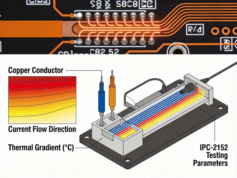
IPC-2152 Current Carrying Capacity Calculation GuideJune/03/2026
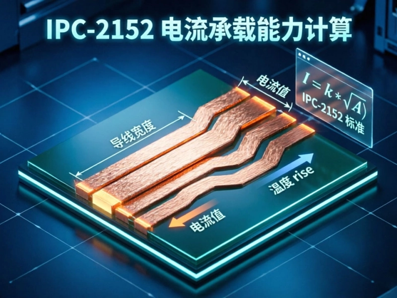
Mastering IPC-2152 Current Carrying Capacity Calculation for Reliable PCB DesignJune/04/2026
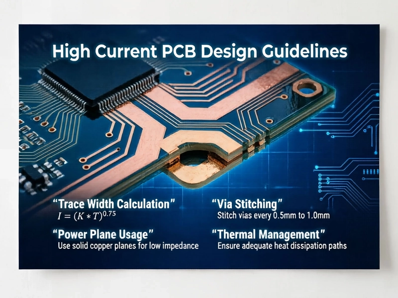
High Current PCB Design Guidelines: Ensuring Reliability and SafetyJune/08/2026
Designing a High Current PCB for Industrial Welding EquipmentJuly/23/2026