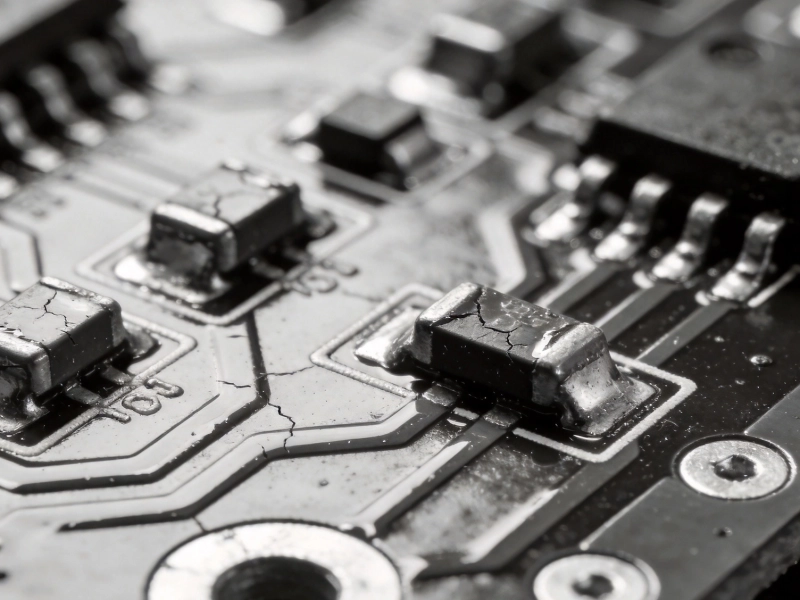
Choosing the wrong PCB material for High Current applications can lead to thermal failures, delamination, and catastrophic board damage.
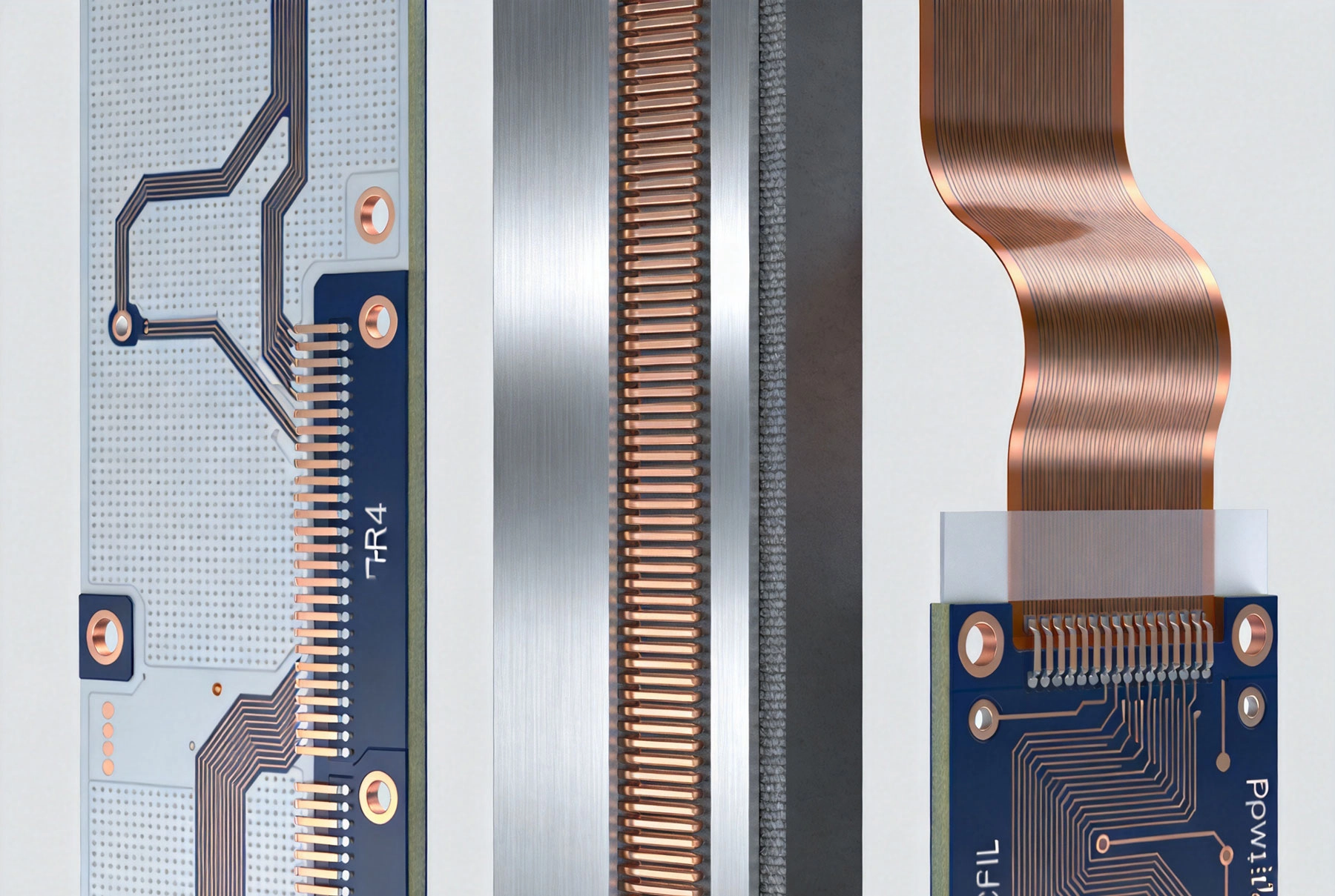
When your Pcb Design carries more than 2-3 amps per trace, material selection becomes critical. Standard FR4 works fine for most electronics, but High Current applications demand better Thermal Management, mechanical stability, and electrical performance. This is where the battle between FR4, metal-core, and polyimide materials intensifies.
In this comprehensive showdown, we'll compare these three PCB materials across the factors that matter most for high current designs: thermal conductivity, Current Carrying Capacity, cost, reliability, and application suitability.

Why Material Selection Matters for High Current Applications
High Current PCB designs face unique challenges that low-power boards never encounter. When currents exceed several amperes, several problems emerge:
-
Thermal buildup: Trace resistance generates heat proportional to current squared (I²R). Without adequate Heat Dissipation, temperatures rise dangerously.
-
Delamination risk: Excessive heat weakens adhesive bonds between layers, causing boards to separate and fail.
-
Trace degradation: Repeated Thermal Cycling causes copper traces to expand and contract, eventually cracking.
-
Solder joint stress: Thermal expansion mismatches stress component connections.
-
Reduced efficiency: Higher temperatures increase resistance further, creating a destructive feedback loop.
The PCB substrate material directly influences how effectively heat transfers away from traces and components. This thermal performance determines whether your design survives or fails under high current loads.
FR4: The Traditional Choice with Limitations
FR4 (Flame Retardant 4) represents the industry standard for PCB substrates. This fiberglass-reinforced epoxy laminate serves approximately 90% of all PCB applications. But how does it handle high current?
Thermal Performance
FR4's thermal conductivity ranges from 0.3-0.4 W/mK, which is poor compared to alternatives. Heat generated by high current traces essentially stays trapped in the board, raising temperatures significantly.
For a trace carrying 10A continuously, FR4 boards can exceed 100°C at the trace surface, approaching the material's glass transition temperature (Tg) of 130-180°C. At these temperatures, FR4 begins to soften, losing mechanical integrity.
Current Carrying Capacity
On FR4, trace width and thickness determine current capacity. Standard 1oz (35μm) copper on FR4 can safely carry approximately:
-
1A with 10mil traces
-
5A with 50mil traces
-
10A with 200mil traces
However, these ratings assume acceptable temperature rises of 10-20°C. Higher currents require dramatically wider traces, consuming board space.
Advantages of FR4 for High Current
-
Lowest cost: FR4 remains the most economical option, 3-5 times cheaper than metal-core alternatives
-
Wide availability: Every PCB manufacturer produces FR4 boards
-
Proven reliability: Decades of use provide extensive Reliability Data
-
Easy fabrication: Standard processes work well
Limitations for High Current
-
Poor thermal conductivity: Heat Dissipation relies primarily on trace surface area
-
Limited temperature range: Tg typically 130-180°C, inadequate for extreme environments
-
Thermal expansion mismatch: CTE (coefficient of thermal expansion) of 14-17 ppm/°C mismatches copper's 17 ppm/°C
-
Moisture absorption: Can absorb 0.1-0.2% moisture, affecting electrical properties
Best Applications for FR4
FR4 suits high current applications with moderate thermal demands:
-
Consumer electronics with currents under 5-10A
-
Power supplies with adequate airflow or Heat Sinks
-
Motor drivers with intermittent operation
-
Applications where cost constraints outweigh thermal concerns
Metal-Core PCBs: Built for Thermal Performance
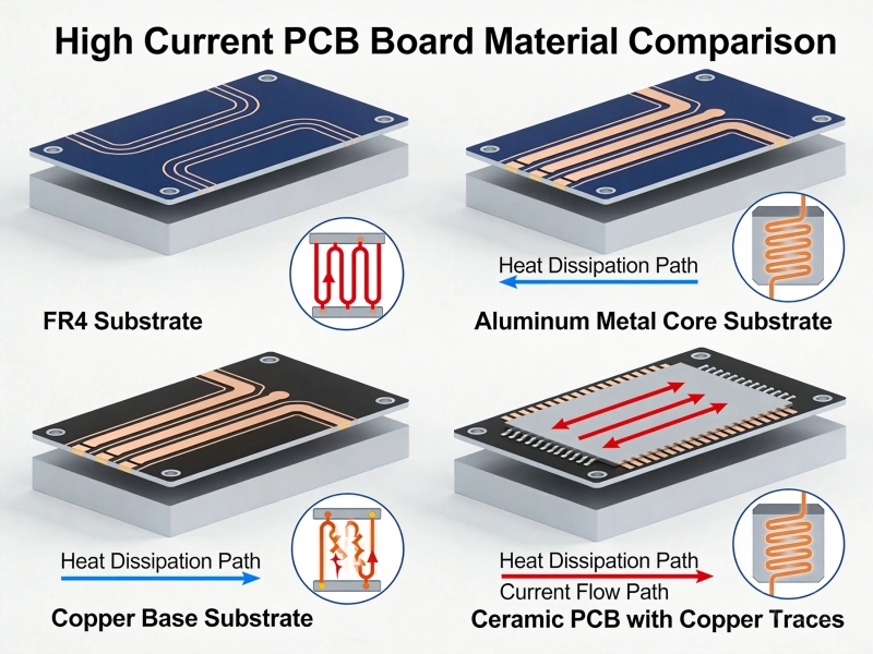
Metal-core PCBs (MCPCBs), also called aluminum-clad or insulated metal substrate (IMS) boards, feature a metal base layer instead of FR4. This construction delivers dramatically better thermal performance.
Construction and Thermal Performance
Typical MCPCB construction includes:
-
Metal base: Aluminum (1-3mm) or occasionally copper
-
Dielectric layer: Thin insulating material with high thermal conductivity (1-3 W/mK)
-
Copper layer: Standard copper foil for circuit traces
The metal core acts as an integrated heat spreader. Thermal conductivity for aluminum MCPCBs reaches 1-2 W/mK, 5-10 times better than FR4. High-performance dielectric layers can achieve 5-8 W/mK.
For that same 10A trace, MCPCBs typically run 30-50°C cooler than FR4, keeping temperatures well within safe operating ranges.
Current Carrying Capacity
MCPCBs handle significantly higher current densities than FR4 for the same trace width:
-
1A with 5mil traces (half FR4's requirement)
-
5A with 25-30mil traces
-
10A with 100-150mil traces
This reduced trace width saves board space, allowing more compact high-power designs.
Advantages of Metal-Core PCBs
-
Excellent Thermal Management: Integrated heat spreading eliminates need for separate Heat Sinks in many applications
-
Higher current capacity: Trace widths can be 40-50% smaller for equivalent current handling
-
Improved reliability: Lower operating temperatures extend component and board life
-
Mechanical stability: Metal core provides rigidity and dimensional stability
-
Simplified assembly: No separate heat sink mounting required
Limitations of Metal-Core PCBs
-
Higher cost: Typically 3-5 times more expensive than FR4
-
Limited layer count: Usually single or double-sided; multilayer versions are rare and expensive
-
Electrical isolation challenges: Dielectric layer must provide adequate insulation from the conductive metal core
-
Via limitations: Traditional plated through-holes connect to the metal core, requiring special design considerations
Best Applications for Metal-Core PCBs
MCPCBs excel in applications where thermal management is critical:
-
LED lighting with high-power arrays
-
Power converters and motor drives
-
Automotive Electronics exposed to high temperatures
-
Power supplies in sealed enclosures without airflow
-
High-current applications exceeding 10-20A per trace
Polyimide: Flexibility Meets High Temperature Capability
Polyimide materials offer unique advantages for high current applications requiring flexibility or operation in extreme environments. Unlike FR4 and metal-core boards, polyimide substrates can bend while handling high temperatures.
Thermal Performance
Polyimide's thermal conductivity remains similar to FR4 at 0.3-0.4 W/mK. However, its exceptional temperature tolerance compensates. Glass transition temperatures exceed 250°C, with some formulations rated for continuous operation at 200-260°C.
This means polyimide can safely operate at temperatures that would destroy FR4. While it doesn't dissipate heat better, it tolerates the heat generated by high currents.
Flexibility Advantages
For applications requiring both high current and physical flexibility, polyimide is unmatched:
-
Minimum Bend Radius of 3-6 times material thickness
-
Dynamic flex capability for moving applications
-
Thin construction (0.05-0.2mm) reduces Thermal Resistance
Advantages of Polyimide for High Current
-
Extreme temperature tolerance: Continuous operation above 200°C possible
-
Flexibility: Enables unique form factors impossible with rigid boards
-
Dimensional stability: Maintains properties across wide temperature range
-
Chemical resistance: Better resistance to solvents and chemicals than FR4
Limitations of Polyimide
-
High cost: 5-10 times more expensive than FR4
-
Moisture absorption: Absorbs 1-3% moisture, significantly higher than FR4, requiring careful storage and processing
-
Poor thermal conductivity: Similar to FR4; doesn't solve heat dissipation challenges
-
Assembly complexity: Requires specialized processes and experienced manufacturers
Best Applications for Polyimide
Polyimide suits specialized high current applications:
-
Flexible circuits in moving assemblies (robotics, foldable devices)
-
Downhole drilling electronics exposed to extreme temperatures
-
Aerospace applications requiring weight savings and flexibility
-
Wearable electronics requiring flexibility with moderate current
-
Applications exceeding FR4 temperature limits but not requiring active cooling
Head-to-Head Material Comparison
Thermal Conductivity Comparison
-
FR4: 0.3-0.4 W/mK (poor)
-
Metal-Core: 1-8 W/mK (excellent)
-
Polyimide: 0.3-0.4 W/mK (poor, but tolerates higher temperatures)
Maximum Operating Temperature Comparison
-
FR4: 130-180°C Tg (limited)
-
Metal-Core: 140-160°C limited by dielectric layer
-
Polyimide: 200-260°C (excellent)
Cost Comparison (Relative to FR4)
-
FR4: 1x (baseline)
-
Metal-Core: 3-5x
-
Polyimide: 5-10x
Current Density Capability
-
FR4: Lowest - requires widest traces
-
Metal-Core: Highest - allows 40-50% smaller traces
-
Polyimide: Similar to FR4 but operates at higher temperatures
Layer Count Flexibility
-
FR4: Excellent - 1-20+ layers common
-
Metal-Core: Limited - primarily 1-2 layers
-
Polyimide: Moderate - 1-6 layers typical for flex designs
Choosing the Right Material for Your High Current Application
Selecting between FR4, metal-core, and polyimide depends on your specific requirements:
Choose FR4 When:
-
Currents are moderate (under 10A per trace)
-
Cost is a primary constraint
-
Multilayer design is required
-
Operating temperatures stay below 120°C
-
Standard manufacturing is preferred
Choose Metal-Core When:
-
Thermal management is critical
-
Currents exceed 10-20A per trace
-
Compact design requires high Current Density
-
Eliminating separate heat sinks simplifies assembly
-
Single or double-layer design is acceptable
Choose Polyimide When:
-
Flexibility is required
-
Operating temperatures exceed 150°C
-
Application involves movement or bending
-
Weight savings are critical
-
Cost constraints allow for premium materials
Hybrid Solutions
Some high current designs combine materials strategically:
-
FR4 + metal-core sections: Use metal-core for high-current areas, FR4 elsewhere
-
Rigid-flex constructions: Combine FR4 and polyimide for 3D assemblies
-
FR4 with Thermal Vias and heat sinks: Enhance FR4's thermal performance when metal-core isn't feasible
Design Tips for High Current PCBs
Regardless of material choice, these design practices improve high current performance:
-
Increase Copper Thickness: Use 2oz or 3oz copper instead of standard 1oz
-
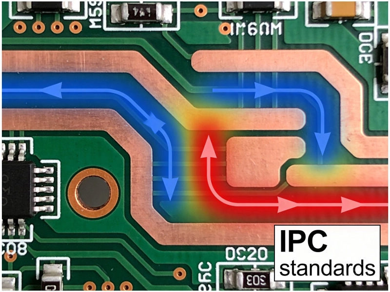
Widen high-current traces: Follow Ipc-2221 guidelines for trace width vs. current
-
Use Thermal Vias: Connect traces to opposite side copper for heat spreading
-
Add copper pours: Maximize copper area around high-current paths
-
Minimize via count: Vias add resistance and Thermal Resistance
-
Consider Component Placement: Position high-current components for optimal thermal flow
Conclusion: Match Material to Application Requirements
There's no universal winner in the FR4 vs. metal-core vs. polyimide showdown. Each material serves specific high current application needs:
FR4 remains the cost-effective choice for moderate high current applications where thermal demands are manageable. Its versatility and wide availability keep it relevant despite thermal limitations.
Metal-core PCBs dominate when thermal management determines success. Their integrated heat spreading capability makes them essential for high-Power Electronics where operating temperature directly impacts reliability.
Polyimide serves specialized applications requiring flexibility or extreme temperature tolerance. While it doesn't solve thermal dissipation challenges, it survives conditions that would destroy other materials.
For high current designs, the material decision should happen early in the design process. Consult with experienced PCB manufacturers who understand thermal performance tradeoffs and can recommend the optimal substrate for your specific application.
Need help selecting the right PCB material for your high current application? Work with manufacturers who provide thermal simulation and material guidance. The right choice upfront prevents costly redesigns and ensures your product performs reliably under demanding conditions.