

Robotics motor controllers operate in one of the most demanding environments in Power Electronics. These systems must deliver high currents with precision timing, manage thermal loads from tens to hundreds of watts, and maintain reliability despite constant mechanical vibration and variable load conditions. Designing the printed circuit board for such applications requires careful attention to electrical and thermal performance—areas where a well-executed Pcb Design directly translates to better robot performance and longer service life.
This guide walks through the critical design considerations for High Current Motor Controller PCBs in robotic systems, from Copper Weight selection to Thermal Management strategies, providing practical guidance for engineers working on the next generation of robotic platforms.
Before beginning Pcb Layout, engineers must understand the actual current levels the Motor Controller will handle. Robotic systems typically employ several motor types, each with distinct current profiles:
The PCB designer must account for both continuous current ratings and transient peaks. Motor startup currents can reach two to three times the steady-state draw. Emergency stops and sudden load changes create even sharper transients. A robust design accommodates these peaks without exceeding temperature limits or causing voltage droop that would affect control circuit performance.
Trace width calculations form the foundation of High Current PCB design. The relationship between Current Carrying Capacity and Trace Geometry follows well-established thermal principles, though real-world implementations require practical adjustments.
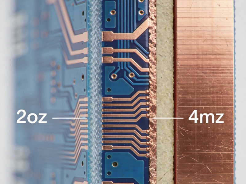
Standard PCB Fabrication offers copper weights from 0.5 oz per square foot (18 microns) for standard boards up to 6 oz or more for Heavy Copper designs. For motor controller applications handling 10 amps or more, designers typically specify 2 oz to 4 oz copper. At these weights, trace widths for 10-amp continuous current typically range from 200 mils to 400 mils depending on acceptable temperature rise.
However, simply widening traces has practical limits. A single trace that is half an inch wide quickly becomes unwieldy on a densely populated controller board. Alternative approaches include:
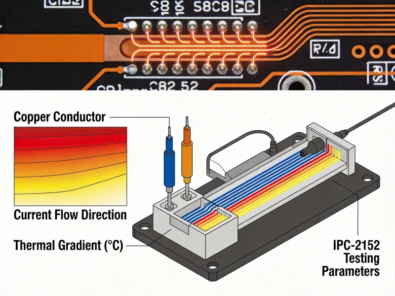
Ipc-2152 provides updated guidance for current-carrying capacity, replacing older standards that tended toward overly conservative estimates. Designers should use Ipc-2152 charts or calculators that account for the specific thermal environment of the motor controller enclosure.
High Current motor controllers generate significant heat that must be managed to maintain reliable operation. The primary heat sources include power MOSFETs or IGBTs in the H-bridge configuration, gate driver circuits, and the copper traces themselves at very high current levels.
Thermal Vias transfer heat from components to inner layers or the board surface where it can dissipate. For motor controller applications, thermal via arrays under MOSFET packages and other power semiconductors dramatically improve heat removal. Via arrays with 1 to 3 mm pitch under the device Thermal Pad work effectively when vias are properly plated with adequate barrel thickness.
For boards where components are mounted on the top side and the bottom can be exposed to air, Thermal Vias provide a direct path for heat to escape. When combined with copper pours on adjacent layers, these via arrays create effective heat spreading planes that reduce hotspot temperatures significantly.
Power semiconductors in motor controller applications typically include exposed thermal pads designed for direct heatsink attachment. The PCB must provide adequate thermal relief during soldering while maximizing heat transfer once the device is populated. Thermal pads with via-in-pad construction—where vias are placed within the Thermal Pad area and filled with solder—provide the best thermal path to internal planes.
When attaching external heatsinks, thermal interface material (TIM) selection matters. Standard thermal greases provide 0.5 to 1.0 °C·in/W Thermal Resistance. Higher-performance materials like phase-change compounds or thermal pads offer convenience in assembly while maintaining good thermal performance.
High-power robotic motor controllers often require active cooling through fans or liquid cooling integration. The PCB designer must coordinate Thermal Management at the board level with the broader system cooling architecture. This includes providing mounting features for fans, designing airflow channels that direct cooling air across the hottest components, and ensuring the PCB and heatsink assembly can survive vibration and Thermal Cycling over the robot's expected service life.
Motor controllers switch high currents at frequencies ranging from 10 kHz to 100 kHz or higher for BLDC commutation. These transitions create voltage transients, conducted noise, and radiated emissions that can disrupt sensitive control circuits and affect electromagnetic compatibility compliance.
Motor driver ICs and gate drivers require local decoupling capacitance close to the device pins to suppress voltage transients during switching. Ceramic capacitors in the 1 µF to 10 µF range placed within 2 mm of the power pins provide the best high-frequency decoupling. For the main power bus, bulk capacitance in the 100 µF to 1000 µF range smooths voltage ripple from the switching cycles.
Snubber networks—typically resistor-capacitor combinations placed across the Mosfet Switching nodes—absorb energy from voltage transients caused by parasitic inductance in the current loop. Proper snubber design requires understanding the specific switching characteristics of the MOSFETs used and the Pcb Layout parasitics. In practice, empirical testing with current probes often guides final snubber component selection.
The motor controller PCB carries both high-current power circuits and sensitive analog and digital control signals. Careful separation prevents noise coupling from the power stage into the control circuits. Guidelines for mixed-signal layout include:
The motor driver section of the PCB must interface cleanly with both the power stage and the control processor. This integration point deserves careful attention during layout.
MOSFET gate drivers require careful layout to deliver clean, fast switching transitions. Gate drive traces should be short and wide to minimize inductance. The gate resistor—typically 10 ohms to 47 ohms—should be placed close to the MOSFET gate pin rather than near the driver IC. A separate gate drive power supply, often generated with small isolated DC-DC converters, prevents noise from the main bus from affecting switching performance.
Current feedback enables closed-loop motor control, overcurrent protection, and torque limiting. Shunt resistors placed in the motor current path provide a voltage proportional to current flow. The amplifier measuring this voltage must be located physically close to the shunt to minimize noise pickup, and the trace routing must use Kelvin connections that exclude the voltage drop across solder joints and vias.
For currents above 30 amps, low-value shunt resistors (typically 1 milliohm to 5 milliohms) keep power dissipation manageable while providing sufficient voltage for accurate measurement. The resulting signal—often only a few hundred millivolts—requires careful amplification and filtering to extract useful information from the noisy motor drive environment.
Robotic motor controllers benefit from multiple layers of protection including:
These protection circuits must be placed strategically to catch fault conditions before they damage expensive components or create safety hazards in the robotic system.
Robot motor controllers face mechanical challenges that differ from most Power Electronics applications. Constant vibration, potential impact forces, and long service life requirements all influence Pcb Design decisions.
PCB mounting within the robot should use vibration-damping features where possible. Within the PCB itself, heavy components such as capacitors and heatsinks benefit from adhesive bonding or staking compounds that prevent mechanical fatigue of solder joints under sustained vibration. Larger through-hole components that protrude above the board surface face greater mechanical stress and may require additional lead support or corner fillets.
Motor controller PCBs typically interface with motors, encoders, power supplies, and the main robot controller through connectors and wiring. Connector footprint design should account for mechanical strain relief—direct cable pull on the connector should not stress the PCB pads. Screw-terminal blocks rated for the appropriate current provide secure, field-serviceable connections for motor leads and power input.
The PCB mounting scheme must ensure reliable ground connection to the robot chassis while maintaining electrical isolation where required. Some motor controller designs integrate onto the same board as the main robot processor, while others use a modular approach with high-speed connectors between boards. The choice affects both EMI performance and serviceability—modular designs simplify field replacement but introduce additional connector resistance in high-current paths.
High Current PCB designs for robotics often push fabrication limits. Communicating requirements clearly to the manufacturer prevents misunderstandings that could compromise reliability.
For boards requiring both fine-pitch control circuitry and heavy copper power delivery, a hybrid approach using heavy copper for power sections while maintaining standard geometry for control sections offers a practical manufacturing compromise.
A well-designed motor controller PCB requires thorough testing to verify performance before deployment in a robotic system. Key test procedures include:
Documenting thermal and electrical performance during development provides a baseline for troubleshooting field issues and validating design changes over the product lifecycle.
For 20-amp continuous current on an outer layer with 10°C temperature rise, approximately 500 mil to 600 mil (about half an inch) of trace width in 2 oz copper is required. In practice, using 3 oz or 4 oz copper allows narrower traces, or you can use copper pours with thermal relief to maximize area within routing constraints.
Sealed enclosures require external Heat Dissipation through the enclosure walls or dedicated Heat Sinks with thermal interface to the chassis. Calculate the Thermal Resistance path from the heat source through the PCB, thermal interface material, enclosure, and finally to ambient air. Active cooling with fans is often necessary for motor controllers above 100 watts.
Four layers typically suffice for motor controllers up to about 30 amps with moderate control complexity. The recommended stackup places Power Planes on the inner layers with signal layers on the outer surfaces. Six or more layers become beneficial for controllers with high-speed communication interfaces, complex mixed-signal circuits, or when additional ground plane isolation improves EMI performance.
Motor starting currents and load transients cause current spikes up to three times the steady-state current. The PCB must provide adequate decoupling capacitance to supply this transient current without voltage droop that could reset control circuits. Including bulk capacitors rated for the peak current and placing them close to the motor driver input prevents voltage collapse during transients.
Ground plane design critically affects both electrical performance and EMI. A solid ground plane under high-current switching nodes provides a low-inductance return path and reduces radiated emissions. However, ground plane cuts or slots around sensitive analog circuits prevent noise coupling from the power stage. The best approach uses a single ground plane with careful separation of analog and power grounds connected at a single point near the power input.
Designing high current PCBs for robotic motor controllers requires balancing multiple technical constraints including current delivery, thermal management, noise immunity, and mechanical robustness. Successful designs start with accurate understanding of the current levels and thermal environment, then apply appropriate copper weights, via strategies, and Component Placement to meet those requirements.
Thermal management deserves early attention since changes late in the design cycle become expensive or impractical. Similarly, protection circuitry and proper decoupling laid out carefully from the beginning create a reliable foundation that simplifies debugging and field support.
Manufacturing considerations—particularly copper weight, hole plating, and surface finish—must be communicated clearly with the fabrication partner to ensure the board as built matches the design intent. Thorough testing under realistic load conditions validates thermal and electrical performance before the controller enters service in the demanding robotic environment.
Ready to explore motor controller PCB design options for your robotic application? Consult with an engineering team experienced in power electronics for custom solutions tailored to your specific performance and reliability requirements.
High Current PCB Design for Uninterruptible Power Supplies (UPS)September/02/2026
5 Critical Thermal Management Problems in High Power PCBsMay/21/2026
Designing a High Current PCB Motor Driver: Avoiding EMI PitfallsJuly/14/2026
High Current PCB Trace Width Calculator: The Ultimate Engineering GuideMay/20/2026
IPC-2152 Current Carrying Capacity Calculation GuideJune/03/2026
High Current PCB Design for High-Power LED DriversAugust/12/2026
2oz vs. 4oz Copper: Which is Best for Your High Current PCB?July/10/2026
Designing a High Current PCB for Industrial Welding EquipmentJuly/23/2026