

Railway traction systems represent some of the most demanding applications for Power Electronics. These systems control massive electric motors that propel trains, trams, and high-speed rail vehicles, requiring PCB designs capable of handling hundreds to thousands of amperes while maintaining reliability under extreme environmental conditions. Unlike industrial or consumer applications, railway electronics must withstand vibration, temperature extremes, electromagnetic interference, and decades of continuous operation. This article explores the critical design considerations for High Current PCBs in railway traction applications, from material selection to Thermal Management strategies.
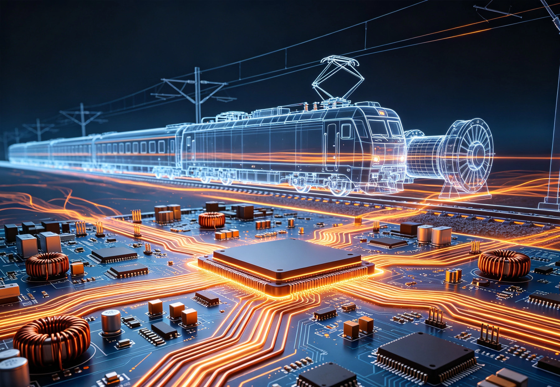
Railway traction systems operate at power levels that dwarf most conventional electronic applications. A typical regional train might require traction inverters delivering 500-1000 amps at 600-750VDC, while high-speed rail systems can demand several thousand amperes during acceleration. These currents flow through PCBs that must maintain stable electrical performance while managing significant heat generation.
The nature of railway power delivery creates unique challenges. Traction inverters switch at frequencies ranging from a few hundred hertz to several kilohertz, generating harmonic content that propagates through Power Distribution networks. Motor regeneration during braking can cause voltage transients that stress insulation systems. Understanding these operational characteristics forms the foundation for sound Pcb Design.
Beyond steady-state current requirements, designers must account for transient conditions. Motor starting currents can exceed nominal operating currents by factors of 1.5 to 2.0. Short-circuit conditions must be cleared rapidly without damage to PCB conductors. These transient scenarios influence both conductor sizing and the selection of protective circuitry.
The substrate material determines fundamental capabilities for High Current, high temperature operation. Standard FR-4 epoxy-glass, while adequate for many applications, reaches limitations in railway traction environments. Glass transition temperatures (Tg) of 130-140°C may prove insufficient when internal PCB temperatures approach elevated ambient conditions.
High-Tg FR-4 materials with Tg values exceeding 170°C offer improved thermal margins. However, for the most demanding applications, polyimide or ceramic substrates provide superior thermal performance. Polyimide films maintain integrity at temperatures reaching 260°C, accommodating both elevated operating temperatures and the thermal excursions during solder assembly. Ceramic substrates, though more expensive, offer excellent thermal conductivity that simplifies heat removal from high current regions.
Material selection must also consider flame resistance requirements. Railway equipment typically requires compliance with UL 94 V-0 flammability ratings. Most high-performance PCB materials satisfy this requirement, but verification remains essential. Documentation from material suppliers should confirm compliance with relevant railway flammability standards.
Determining appropriate conductor dimensions for high current PCBs requires careful analysis. The Ipc-2152 standard provides baseline guidance for current-carrying capacity, but railway applications often demand more conservative approaches. Temperature rise within conductors generates several consequences: reduced efficiency through I²R losses, potential damage to adjacent components from elevated temperatures, and accelerated aging of insulation materials.
For currents exceeding 100 amperes, standard trace widths become impractical. Heavy Copper PCBs with 3-10 ounce copper or thicker provide the necessary conductor cross-section. At these current levels, designers typically employ dedicated Power Planes rather than discrete traces. Power Planes offer superior Current Distribution, reduced impedance, and improved thermal spreading compared to narrow conductors.
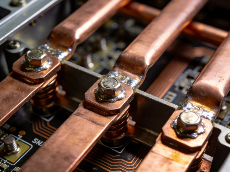
Bus Bar integration often proves necessary for the highest current paths. Rather than relying solely on PCB conductors, designers incorporate discrete copper bus bars that bolt directly to PCB termination points. These bus bars provide current capacity impossible to achieve within PCB constraints while also serving as Thermal Management elements. The interface between bus bars and PCB requires careful design to ensure reliable electrical connection and adequate heat transfer.
Heat management determines the viability of High Current PCB designs. Every ampere flowing through resistance generates heat according to the I²R relationship. A 1000-ampere Bus Bar with just 1 milliohm of resistance dissipates 1000 watts—energy that must be removed to prevent catastrophic failure.
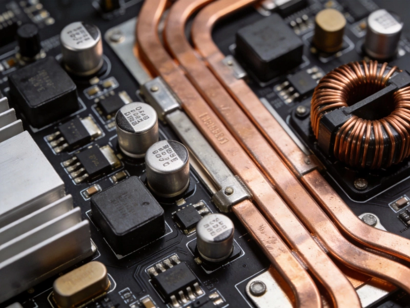
Thermal Vias provide the primary mechanism for transferring heat from PCB internal layers to external surfaces or dedicated Heat Sinks. Via arrays surrounding high-power components create thermal paths with resistance measured in degrees Celsius per watt. For critical components, Thermal Relief Patterns around pads facilitate solder connection to external Heat Sinks while minimizing Thermal Resistance.
Metal core PCBs (MCPCBs) offer superior thermal performance compared to standard substrates. Aluminum or copper cores conduct heat away from power devices with thermal conductivity many times greater than FR-4. These substrates integrate directly with mechanical heat sinks, creating efficient thermal pathways. The trade-off involves increased manufacturing complexity and reduced flexibility for routing dense signal traces.
Active cooling through forced air or liquid circulation becomes necessary for the highest power densities. Designers must coordinate Pcb Thermal Design with overall system cooling architecture. Component Placement should consider airflow patterns, preventing hot spots and ensuring even temperature distribution across the assembly.
Railway systems operate at voltages that require substantial isolation distances. Traction supply voltages of 750VDC or 1500VDC exceed safe touch voltages by considerable margins. Pcb Design must incorporate creepage and clearance distances that prevent arcing between conductors under contaminated or humid conditions.
Creepage distance—the shortest path along an insulating surface between two conductors—must account for pollution and moisture. According to IEC 60664-1, pollution degree 2 environments require increased creepage for working voltages above 320V. Railway equipment often faces pollution degree 2 or even pollution degree 3 conditions, necessitating enlarged isolation zones.
Conformal coating provides additional protection for high-voltage circuits. Acrylic, urethane, or parylene coatings increase effective creepage distances by preventing surface contamination and moisture absorption. However, coatings require compatible material selection for adjacent components and careful application to ensure complete coverage of critical isolation zones.
Isolation transformers and optocouplers provide galvanic isolation between traction circuits and low-voltage control electronics. Pcb Layout must maintain adequate separation between isolated circuits, considering both creepage and clearance requirements. Designers should verify isolation boundaries during layout review, ensuring no unintended coupling paths compromise safety isolation.
Railway environments expose electronics to aggressive contaminants including dust, moisture, salt (particularly in coastal operations), and chemical exposure from brake systems. Without protection, these contaminants can compromise insulation resistance, promote corrosion, and ultimately cause field failures.
Conformal coating application becomes nearly mandatory for traction control electronics. The coating choice depends on operating conditions: acrylic coatings offer general-purpose protection with good reworkability, urethane coatings provide superior chemical resistance, silicone coatings accommodate Thermal Cycling better than most alternatives, and parylene coatings deliver exceptional uniform coverage for miniaturized assemblies.
Application method influences both cost and coverage quality. Spray coating suits high-volume production of larger assemblies. Selective coating systems apply material only to designated areas, protecting connectors and test points automatically. For prototype quantities, brush or dip application may prove more economical despite increased labor content.
Critical design considerations for coated assemblies include accounting for dimensional changes during Thermal Cycling, ensuring adequate adhesion promotion for smooth surfaces, and providing access points for test and rework. Components requiring field replacement should incorporate sockets or service loops that facilitate removal without destroying adjacent coating.
Railway vehicles generate continuous vibration from wheel-rail interaction, motor rotation, and aerodynamic sources. This vibration transmits through vehicle structures to electronic equipment, creating mechanical stresses that can compromise solder joints, loosen fasteners, and fatigue trace metallization over operational lifetimes measured in decades.
PCB mounting design must accommodate vibration while preventing resonant amplification. Rigid mounting to vehicle structure transmits all vibration energy to assemblies. Vibration isolation mounts introduce compliance that reduces acceleration atpcb locations, though isolation introduces its own challenges for maintaining electrical connections.
Component selection for vibration environments favors packages with robust lead configurations. Edge-mounted components with Gull-wing leads offer superior fatigue resistance compared to J-lead packages. Through-hole components with long leads can act as tuning forks, amplifying vibration at resonant frequencies. Lead-free Solder alloys exhibit higher Young's modulus than tin-lead solders, increasing stress at component interfaces and potentially accelerating fatigue failures.
Printed circuit board reinforcing through back-potting or full encapsulation can improve mechanical robustness for critical applications. These processes add mass and damping that reduce vibration amplitudes at critical frequencies. However, potted assemblies become difficult or impossible to rework, so this approach suits high-reliability applications where field serviceability is not a primary concern.
Power Electronics switching at kilohertz frequencies generate electromagnetic interference spanning from fundamental switching frequencies through radio frequency harmonics. Traction inverters produce conducted emissions that propagate through Power Distribution networks and radiated emissions that can interfere with vehicle communication systems.
Pcb Layout directly influences both generated interference and susceptibility to external fields. High current switching loops should be minimized through careful Component Placement. Gate drive traces for IGBTs and MOSFETs must be short and matched to prevent ringing and overshoot that increase EMI generation.
Grounding strategy affects both conducted and radiated emissions. Single-point grounding for low-frequency circuits minimizes ground loops that can amplify interference. Multi-layer PCBs often dedicate entire layers as ground planes, providing low-impedance return paths that reduce antenna effects from signal traces.
Shielding requirements may extend beyond PCB-level design to encompass entire enclosures. Conductive gaskets maintain shielding effectiveness at enclosure seams while allowing thermal expansion. Cable penetrations require filtered feedthroughs that prevent EMI leakage through conductors. These system-level considerations complement PCB design practices to achieve overall EMC compliance.
Railway electronics must satisfy numerous standards governing design, testing, and documentation. The EN 50155 standard covers electronic equipment for railway applications, specifying requirements for operating temperature range, power supply compatibility, vibration and shock resistance, and electromagnetic compatibility. Compliance with EN 50155 typically requires testing at accredited laboratories with documentation of test results.
EMC compliance requires meeting both conducted and radiated emission limits specified in EN 50121-3-2 for railway vehicle applications. These limits ensure that electronic equipment does not interfere with train communication systems, signaling equipment, or passenger entertainment systems. Pre-compliance testing during design development helps identify and address potential issues before formal certification testing.
Environmental testing according to EN 60068 verifies performance under temperature extremes, humidity, and vibration conditions. Extended temperature range testing from -40°C to +70°C (or higher for equipment near traction motors) ensures components remain functional throughout vehicle operating conditions. Thermal cycling testing identifies weaknesses in solder joints and component attachments that might fail during thermal excursions.
High Current PCB design for railway traction systems demands expertise spanning multiple engineering disciplines. Electrical designers must calculate conductor sizing for ampere-level currents while managing thermal and mechanical constraints. Mechanical considerations influence material selection, mounting design, and protection strategies. Compliance with railway standards requires systematic documentation and testing that validates design decisions.
The rewards of successful design extend beyond technical performance. Railway operators require equipment that operates reliably for decades with minimal maintenance. Passengers and freight depend on traction systems functioning correctly throughout environmental extremes and thousands of operating hours. Understanding the unique challenges of railway traction applications enables engineers to create designs that meet these demanding requirements.
Whether developing new traction inverters, retrofitting legacy equipment, or specifying assemblies for railway applications, partnering with manufacturers experienced in high current, high-reliability PCBs accelerates project success. The investment in proper design practices and qualified manufacturing yields equipment that performs reliably throughout its operational life.
High Current PCB Design for Medical Imaging EquipmentSeptember/10/2026
High Current PCB Design for Renewable Energy MicrogridsSeptember/30/2026
High Current PCB Design for Drone ESCs: Minimizing Loop InductanceAugust/03/2026
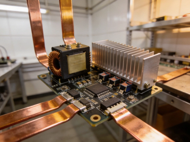
High Current PCB Design for High-Power LED DriversAugust/12/2026
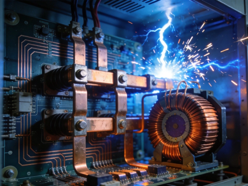
High Current PCB Design for High-Voltage DC TransmissionSeptember/24/2026
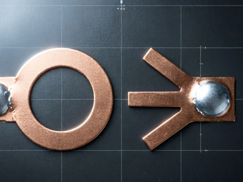
High Current PCB Thermal Relief: Full Connect vs. Modified SpokesJuly/16/2026
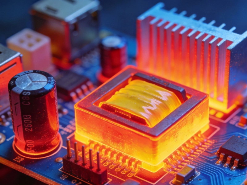
High Current PCB Design for High-Frequency Switching RegulatorsSeptember/04/2026
High Current PCB Design for Uninterruptible Power Supplies (UPS)September/02/2026