

When your Pcb Design needs to handle tens or hundreds of amps, ordinary copper traces quickly reach their limits. Standard PCB Fabrication processes were designed for signals, not power. The Copper Weight, trace width, and Thermal Management techniques that work for low-current circuits simply do not scale to the demands of Power Electronics. This is where plated slots and Heavy Copper bus bars become essential design tools.
This article compares plated slots against standard Heavy Copper traces for extreme current applications, examining the physics of Current Carrying Capacity, thermal implications, manufacturing considerations, and practical guidance for choosing the right approach for your design.

The fundamental challenge with Pcb Current carrying is heat. Every conductor carrying current generates heat according to Ohm's law. As current increases, the heat generated grows with the square of the current. At some point, the temperature rise becomes unacceptable, leading to degradation of solder joints, laminate damage, or complete failure.
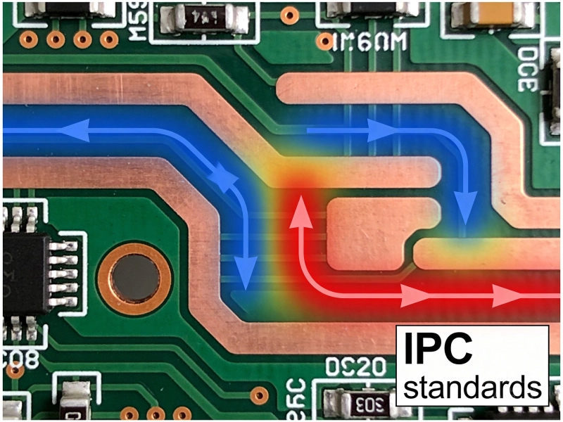
Ipc-2152 provides updated guidance on Current Carrying Capacity, replacing the older Ipc-2221 charts. The standard accounts for factors including Copper Thickness, trace width, ambient temperature, altitude, and whether the trace is on an external or internal layer. For standard external layer traces at 1 oz copper, practical limits typically top out around 10-15A before trace widths become impractically large.
The situation becomes more challenging when you need to carry 30A, 50A, or more. At these current levels, standard approaches yield trace widths that may exceed the board dimensions themselves. This is where alternative strategies become necessary.
The simplest approach to increasing current capacity is using heavier copper. Standard PCB Fabrication typically uses 1 oz copper per square foot, which produces approximately 1.4 mils (35 micrometers) of Copper Thickness. Heavy copper processes can produce 2 oz, 3 oz, 4 oz, or even thicker copper, directly increasing the cross-sectional area available for current flow.
Heavy copper traces offer several advantages. They are a straightforward extension of standard Pcb Manufacturing processes. The routing follows normal design practices, making layout and routing software work normally. Heavy copper boards can often be fabricated by the same manufacturers that produce standard boards, with appropriate lead times.
However, heavy copper traces have limitations. The copper thickness adds cost, and very thick copper requires specialized processing. At extreme current levels, even 4 oz or 6 oz copper may not provide sufficient cross-sectional area. Additionally, heavy copper traces on external layers may require specialized surface finishes to ensure reliable solderability.
Plated slots represent an alternative approach to extreme current carrying. Rather than routing current through a Copper Trace, plated slots use elongated via structures plated with thick copper to create conductors that more closely resemble bus bars. The slot is routed through the PCB substrate, and the walls of the slot are plated with copper, creating a conductive channel.
The key advantage of plated slots is their cross-sectional area. A slot that is 100 mils wide by 400 mils long, plated to 3 mils thickness on all surfaces, provides substantially more copper volume than a trace of equivalent width. This translates directly to higher current carrying capacity and better thermal performance.
Plated slots also offer superior thermal dissipation. The slot geometry provides more surface area in contact with the PCB dielectric, improving heat transfer away from the current-carrying conductor. This becomes increasingly important at higher current levels where Thermal Management is the primary constraint.
Thermal management is the dominant consideration in High Current PCB design. The temperature rise in a conductor depends on the power dissipation, the Thermal Resistance to the surrounding environment, and the thermal properties of the materials involved.
For plated slots, the thermal path is more complex but generally more favorable. Heat generated in the slot can dissipate through the plating into the dielectric material, through any Thermal Vias to internal planes, and through the surface area of the slot walls. This multiple-path thermal architecture provides better heat spreading than a simple trace on a surface.
Several strategies improve thermal performance for both approaches. Adding Thermal Relief Patterns around component connection points prevents heat from being concentrated at solder joints. Thermal Vias near high-current pathways provide additional thermal paths to internal planes or back-side cooling surfaces. For extreme applications, metal core substrates or embedded coin heat spreaders may be necessary.
The choice between slots and traces also affects electromagnetic considerations. Slots create more complex return current paths and may affect Emi performance. For applications where electromagnetic emissions matter, careful attention to slot placement and ground plane continuity is essential.
Plated slots require specialized manufacturing processes that not all PCB fabricators support. The plating process must achieve consistent thickness on vertical surfaces, which is mechanically challenging. Slots also create stress concentration points in the laminate, requiring careful consideration of board thickness and slot geometry to prevent cracking.
Aspect ratio becomes critical for plated slots. The depth-to-width ratio of the slot affects plating uniformity and manufacturing yield. Most manufacturers can produce reliable slots with aspect ratios up to approximately 3:1, but higher ratios may require specialized processing or multiple plating steps.
Slot geometry also affects Manufacturing Cost. Rounded ends are gentler on the plating process and reduce stress concentration. Sharp corners create plating challenges and potential reliability issues. Budgeting for generous corner radii improves manufacturability and reliability.
Heavy copper traces are more straightforward to manufacture but still require attention to process capabilities. Very thick copper may require specialized imaging and etching processes to achieve clean edges. Overhang at trace edges, where etchant attacks copper from beneath the resist, becomes more pronounced with heavier copper weights.
Differential etching is another consideration. When a board combines fine-pitch components requiring thin traces with heavy copper power conductors, the etching process must be balanced to avoid under-etching fine features while adequately removing copper from wide areas. Some fabricators handle this with multiple etching steps or plate-and-etch processes.
Effective plated slot design requires attention to several key parameters. The slot length should be maximized to increase surface area for Heat Dissipation. The slot width must be sufficient for adequate plating coverage and copper thickness. The corner geometry should use generous radii to minimize stress concentration and improve plating quality.
Connection to plated slots requires careful consideration. Solder fillet formation at slot ends differs from standard pad connections. Designing adequate landing areas and using Thermal Relief Patterns where slots connect to component pads ensures reliable solder joints. For very high currents, bolt-on Bus Bar connections may be more appropriate than soldering.
Slot placement should consider the PCB stackup and layer count. Slots that penetrate multiple layers create complex interactions with internal planes and routing. For designs with controlled impedance or sensitive signal routing, slot placement must be coordinated with the overall layer strategy to avoid unintended electromagnetic effects.
Heavy Copper Trace design follows standard PCB routing practices with some modifications. The minimum line width may be constrained by the Copper Weight, as very thick copper is difficult to image and etch at fine geometries. Consult with your fabricator on achievable minimum line widths for your chosen copper weight.
Spacing between heavy copper traces and other features requires additional margin. The thicker copper creates a taller profile that affects solder mask coverage and clearance to adjacent features. Standard design rules may need adjustment to account for the increased copper height.
For applications above approximately 50A, consider combining heavy copper traces with other current-carrying strategies. Wide traces supplemented with bus bars, additional copper planes on adjacent layers connected with stitching vias, or metal backplates can achieve current capacities that would be impractical with traces alone.
Both plated slots and heavy copper traces have their place in High Current PCB design. The choice depends on current requirements, thermal constraints, manufacturing capabilities, and cost considerations.
Heavy copper traces are preferable when the current requirement can be met with copper weights up to 4 oz, when the layout can accommodate wide traces, and when manufacturing simplicity is valued. They work well for continuous current paths where the routing can follow the required trace width.
Plated slots become advantageous for very high currents, typically above 30-40A, where trace widths would become impractically large, where superior thermal dissipation is needed, and where the slot geometry fits the design layout. They are particularly valuable for Bus Bar replacements and where current must be concentrated in specific pathways.
Many designs benefit from combining both approaches. Heavy copper traces might handle moderate Current Distribution across the board, while plated slots concentrate current at the highest-density points. This hybrid approach optimizes both manufacturing efficiency and performance.
Extreme current designs push the boundaries of standard Pcb Reliability. Plated slots introduce mechanical stress concentration that may affect long-term durability under Thermal Cycling. Heavy copper traces can create differential expansion stresses at component interfaces.
Thermal Cycling is particularly challenging. The coefficient of thermal expansion of copper differs significantly from the PCB laminate. Over many thermal cycles, this mismatch can cause fatigue in plated vias, solder joints, and slot-plating interfaces. Designs expected to undergo frequent thermal cycling should include margin for these effects.
Accelerated life testing is advisable for extreme current designs. Thermal imaging under load conditions, thermal cycling to verify solder joint integrity, and current stress testing to identify weak points all contribute to design validation. The investment in testing is small compared to field failures.
Extreme current Pcb Design benefits from early engagement with your fabrication partner. Provide clear current requirements, expected thermal conditions, and any special requirements such as thermal testing or extended life testing. A good manufacturer can advise on achievable parameters and flag potential issues before design completion.
Request cross-section samples from prototype boards to verify plating quality and uniformity. The plating thickness in a slot is not always visible from external inspection, and cross-sectioning provides definitive verification that the manufacturing process achieved the required copper thickness.
For very demanding applications, consider working with manufacturers that specialize in Power Electronics. These shops have experience with the process controls and quality assurance procedures specific to high-current manufacturing and can provide guidance based on similar past projects.
Designing PCBs for extreme currents requires moving beyond standard trace guidelines and embracing the specialized techniques available for power electronics. Both plated slots and heavy copper traces have roles to play, and many successful designs combine both approaches.
The key is understanding the underlying physics of current carrying and thermal management, then applying that understanding to select the approach that best fits your specific requirements. With careful design, good manufacturing partnerships, and appropriate testing, PCBs can reliably handle currents that would have seemed impossible just a decade ago.
While the exact threshold depends on available board space and thermal requirements, plated slots typically become advantageous above approximately 30-40A. Below this range, heavy copper traces up to 4 oz can usually meet requirements. Above this range, trace widths become impractical, and slots or bus bar alternatives become necessary.
Not all manufacturers can produce plated slots reliably. The process requires specialized plating capabilities and process control. Before designing with plated slots, verify with your manufacturer that they can meet your requirements for slot geometry, copper thickness, and plating uniformity. Many quick-turn services do not support plated slots.
Plated slot current capacity depends on the total copper cross-section, which includes the perimeter plating thickness times the slot perimeter plus any internal plating. Thermal considerations are more complex than for traces because Heat Dissipation paths are multidimensional. Ipc-2152 provides some guidance, but extreme current designs often rely on thermal simulation and empirical testing.
Typical plated slot copper thicknesses range from 1 mil to 3 mils (25-75 micrometers) depending on the manufacturer and process. Thicker plating is possible but requires multiple plating steps and significantly longer processing time. Some specialty manufacturers can achieve plating up to 5 mils or more.
Yes, slots create stress concentration and reduce mechanical strength. Slots should be placed away from board edges and mounting holes where possible. For applications requiring mechanical robustness, consider thicker board materials or additional structural support around slots. Rigid-flex designs with slots in rigid sections can manage the trade-offs more effectively.
High Current applications generally favor finishes that maintain conductivity and solderability without adding unnecessary layers. Immersion silver, Enig, and bare copper with organic solderability preservatives each have trade-offs. For bolted connections, bare copper with silver plating or nickel plating provides the best contact resistance.
High Current PCB Design for High-Power RF AmplifiersOctober/10/2026
How Much Current Can a PCB Trace Carry? Complete Engineering GuideMay/20/2026
High Current PCB Solder Wicking: Tented Vias vs. Untented ViasSeptember/01/2026
High Current PCB Component Placement: Grouping vs. Distributed LayoutJuly/21/2026
High Current PCB Annular Rings: Minimum Size vs. Reinforced SizeAugust/12/2026
A Deep Dive into High Current PCB Design for Solar InvertersJuly/17/2026
Bus Bar vs PCB Trace for High CurrentMay/21/2026
High Current PCB Solder Joints: Wave Soldering vs. Selective SolderingJuly/15/2026