

Electric aircraft represent one of the most demanding applications for Power Electronics, combining the need for extreme reliability with high power density, strict weight constraints, and operation across wide temperature ranges and high altitude conditions. The power systems in electric aircraft, including motor controllers, battery management units, Power Distribution modules, and charging interfaces, all depend on PCBs that must carry substantial currents while maintaining thermal stability, electrical isolation, and mechanical integrity under conditions that would challenge conventional Industrial Electronics. Designing PCBs for these applications requires a thorough understanding of aviation safety standards, Thermal Management at altitude, and the reliability requirements that govern certified aerospace systems.
This article examines the key considerations for High Current PCB design in electric aircraft power systems, covering the unique challenges of aviation environments, material selection, Thermal Management strategies, and the manufacturing and qualification requirements that determine whether a design can achieve the reliability needed for flight certification.
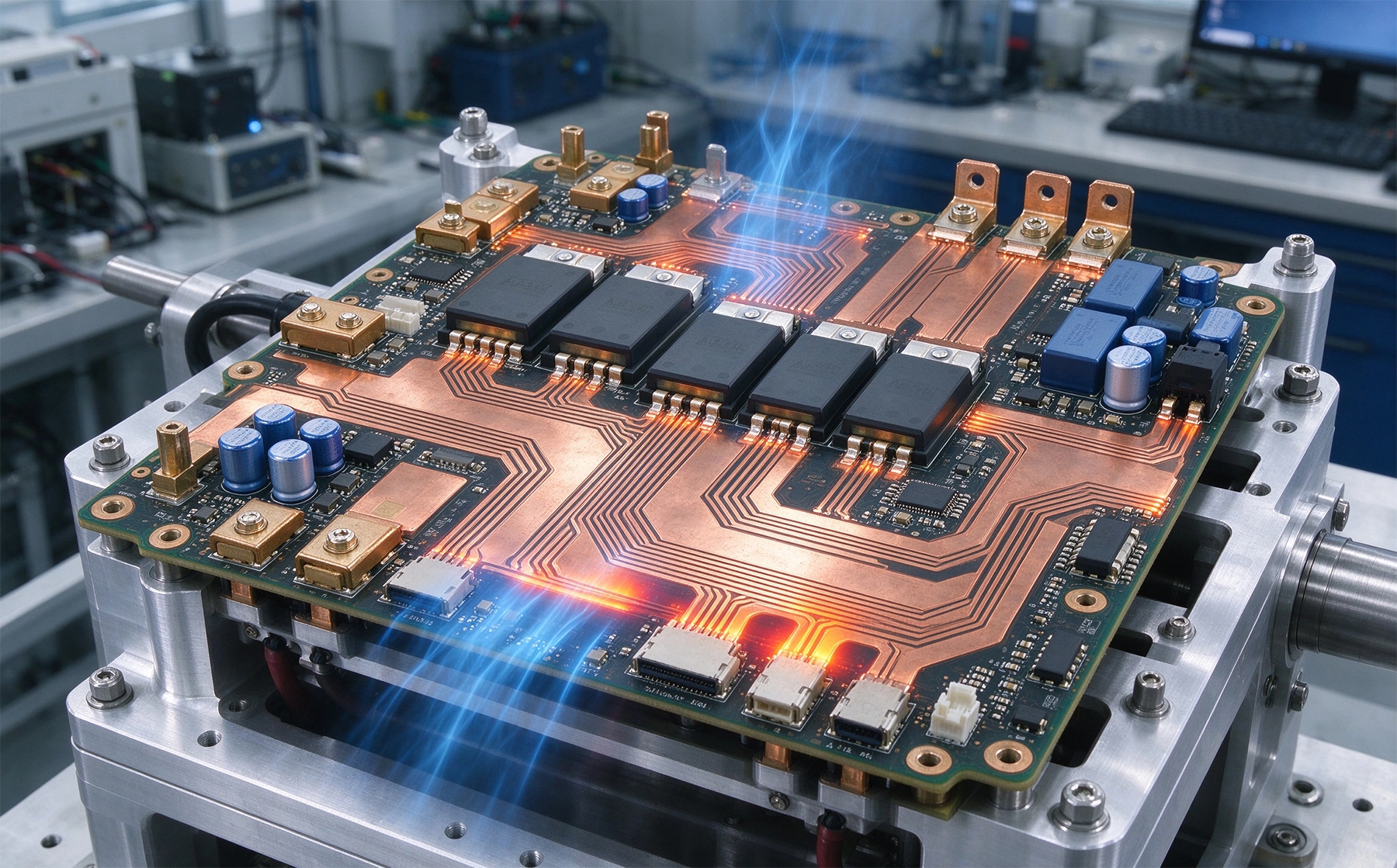
Electric aircraft create Pcb Design challenges that differ substantially from ground-based or industrial applications. Understanding these environmental factors is the foundation for making appropriate design choices that will survive in service.
Altitude affects both thermal management and electrical breakdown characteristics. As aircraft climb, ambient air pressure drops, reducing the effectiveness of convective cooling. At 35,000 feet, air density is roughly one-quarter of sea level, which means forced-air cooling systems are far less effective and natural convection cooling is severely limited. PCBs that would operate within temperature limits at sea level may overheat at altitude even when they meet thermal targets during ground testing. Design margin calculations must account for the reduced cooling effectiveness at maximum operating altitude.
Temperature extremes in aviation are broader than most industrial applications face. Electric aircraft may need to operate in temperatures below minus 40 degrees Celsius during high-altitude cruise, then transition rapidly to much warmer temperatures near engines or electronic enclosures during ground operations. This Thermal Cycling creates fatigue stress on solder joints, plated vias, and component interfaces that must be designed to survive hundreds or thousands of cycles over the aircraft service life. The rate of temperature change during ascent and descent can also be steep, creating thermal gradients within the PCB that cause differential expansion and additional stress.
Vibration and mechanical shock from propeller operation, turbulence, and landing create mechanical loads that must be withstood throughout the aircraft service life. PCBs in electric aircraft must survive sustained vibration at frequencies determined by motor and propeller speeds, plus occasional high-shock events from turbulence or hard landings. These mechanical loads stress solder joints, cause crack propagation in plated vias, and can loosen connectors or fasteners if the board is not adequately supported.
Safety-critical reliability requirements for flight systems demand failure rates far below what is acceptable in commercial electronics. A failure in a Motor Controller or Battery Management System could cause loss of aircraft control, making the consequences far more severe than most electronic product failures. Aviation standards require demonstrated reliability measured in failures per million flight hours, with rigorous qualification testing to prove the design meets these targets before it can be certified for flight use.
Electric aircraft power systems carry currents that dwarf typical consumer or Industrial Electronics. Motor controllers for electric propulsion may handle hundreds of amps, battery management systems must distribute and monitor currents in the same range, and Power Distribution modules route High Current to multiple loads throughout the aircraft. Designing PCBs to carry these currents reliably requires approaches that go far beyond standard Pcb Design practices.
Trace width calculations for High Current must account for both the DC Current Carrying Capacity and the thermal constraints of the aircraft environment. Standard IPC trace width calculators provide a starting point, but they typically assume convection cooling at sea level pressure, which does not apply at altitude. For electric aircraft designs, trace widths should be calculated using altitude-adjusted thermal models, and generous safety margins should be applied to account for uncertainty in cooling effectiveness and component aging over the service life.
Copper Weight selection for high current traces typically ranges from 3oz to 6oz, with some designs using even heavier copper for the highest current paths. At these copper weights, trace widths become substantial, and routing these traces across the board consumes significant area. Careful planning of the layer stack-up and current path routing is necessary to accommodate high current traces without making the board impractically large. In some cases, bus bars attached to the PCB surface may be more practical than using copper traces for the very highest current paths.
Via design for high current inter-layer connections requires multiple parallel vias with heavy plating to match the current capacity of the traces they connect. A single standard via cannot carry the same current as a wide trace, so current-carrying via arrays must be sized to provide equivalent cross-sectional area. Via barrel plating of 35 microns or more is typically required for high current vias, and the total cross-sectional area of the via array should equal or exceed the cross-sectional area of the narrowest trace carrying that current.
The materials used in aircraft power PCBs must meet requirements for thermal performance, flame retardance, mechanical strength, and long-term stability that exceed typical commercial specifications. Material selection is one of the most consequential decisions in electric aircraft PCB design.
High-Tg FR4 laminates with glass transition temperatures of 170 degrees Celsius or higher are commonly used in aviation Power Electronics because they provide better thermal margin than standard Tg materials. During Motor Controller operation, localized temperatures can reach 100 degrees Celsius or higher in densely packed areas. Using materials with adequate thermal margin above maximum operating temperature ensures that the substrate does not approach its glass transition point during worst-case operation, which would cause loss of mechanical rigidity and potential delamination.
Polyimide-based materials offer additional thermal and mechanical performance for the most demanding applications. Polyimide has higher thermal capability than FR4 and better resistance to Thermal Cycling fatigue, making it appropriate for high-reliability aviation applications where the cost premium is justified. However, polyimide is more expensive and more difficult to process than FR4, so it is typically reserved for the most thermally or mechanically challenging portions of the design rather than used for the entire board.
Metal core substrates may be appropriate for very high power density sections of the power electronics, where the PCB must function as both a circuit substrate and a heat spreader. Aluminum core boards with thermally conductive dielectric layers can spread heat from power components into the metal substrate, which then conducts heat to a chassis-level heat sink or cooling structure. Metal core constructions add complexity and cost but may be the only practical solution for power densities that exceed what FR4-based approaches can dissipate.
Flame retardancy requirements for aviation electronics are more stringent than commercial UL standards. Materials must meet FAR 25.853 requirements for flame retardance, smoke density, and toxicity, which require specific material selections and potentially longer processing times to achieve the required performance. Not all PCB materials meet these requirements, so material selection must be verified against the specific flame test requirements for the intended aircraft category and installation location.
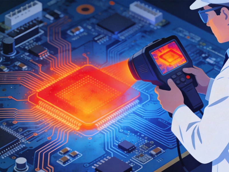
Thermal management in electric aircraft power systems must be designed for the most challenging conditions: high altitude operation with reduced convective cooling, high power dissipation in densely packed enclosures, and the need to maintain component temperatures below rated limits throughout the aircraft service life.
Heat spreading through copper planes is the primary thermal management mechanism at altitude, because it does not depend on air convection. Designing generous copper planes connected to high-power components through Thermal Vias distributes heat across a larger area, reducing localized temperature rise. The thermal spreading effectiveness of copper planes is independent of altitude, making this approach essential for aircraft applications where convection cooling is unreliable.
Thermal via arrays beneath power components provide the critical thermal path from the component junction through the PCB to inner layer copper planes or to a heat sink attached to the board surface. These vias must be designed with sufficient density and plating thickness to achieve the Thermal Resistance target for the component, accounting for the fact that the external heat sink may be less effective at altitude than ground testing suggests. Thermal simulation during design helps verify that the via array will achieve the required thermal performance, but physical testing at altitude-equivalent conditions is essential for critical aviation applications.
Forced-air cooling remains useful in aircraft applications, but the system must be designed for reduced air density at altitude. Fans and blowers sized for sea-level performance may be inadequate at cruising altitude. Using multiple smaller fans in parallel provides redundancy and may maintain adequate airflow better than a single larger fan, because the parallel configuration continues to function if one fan fails. Computational fluid dynamics simulation helps optimize airflow path and fan selection for the specific enclosure geometry and altitude range.
Electric aircraft power systems often involve voltages that exceed the safe limits for human contact and create risks of arcing or tracking that must be designed against. Battery systems in electric aircraft may operate at 400V or higher, creating both shock hazard and insulation breakdown concerns that affect PCB design throughout the power system.
Clearance and creepage distances between conductors must meet or exceed the requirements of the applicable aviation standards, which may be more stringent than commercial IEC requirements. For 400V battery systems, minimum clearances of 2mm or more between adjacent conductors are typically required, with larger clearances for polluted or high-altitude environments where arcing occurs more readily. These clearance requirements affect the minimum board size for a given circuit complexity and must be accounted for during initial layout planning.
Conformal coating provides additional electrical isolation and environmental protection for boards in high-voltage applications. Acrylic, urethane, or parylene conformal coatings increase the effective creepage distance along the board surface, allowing tighter spacing than would be permissible on an uncoated board. Coating also protects against moisture ingress and contamination that could create tracking paths across the board surface. The coating material and application process must be compatible with the components on the board and must meet flame retardance requirements for the aircraft interior.
Isolation between high-voltage and low-voltage circuits must be maintained throughout the PCB design. Any transformers, optocouplers, or digital isolators that provide isolation between high-voltage and low-voltage domains must be positioned to maintain the required isolation distances on the PCB. Slotting or cutouts in the PCB around isolated regions may be required to maintain clearance across the isolation boundary under all manufacturing and operating conditions.
PCBs for electric aircraft power systems must undergo rigorous qualification testing to demonstrate they meet the reliability requirements for flight certification. This testing goes far beyond what commercial electronics undergo and includes environmental testing, endurance testing, and failure analysis to verify the design will perform reliably throughout the aircraft service life.
Thermal cycling testing exposes boards to repeated temperature extremes representative of the aircraft operating range. Testing to 1,000 cycles or more at temperature ranges from minus 40 to plus 125 degrees Celsius verifies that solder joints, plated vias, and substrate materials can survive the thermal fatigue of repeated flight cycles. Electrical testing before, during, and after thermal cycling monitors for increases in resistance or insulation leakage that would indicate degradation.
Vibration testing validates that the PCB and its components survive sustained vibration at frequencies and amplitudes representative of aircraft operation. Testing may include random vibration profiles, sine sweep testing at resonant frequencies, and shock testing for landing or turbulence events. During vibration testing, boards are electrically monitored for intermittent opens or shorts that would indicate mechanical degradation of solder joints or plated vias.
High voltage testing verifies that isolation barriers maintain adequate breakdown voltage throughout the product service life. Testing at voltages significantly above the maximum operating voltage, while monitoring for tracking or breakdown, verifies that clearances, conformal coatings, and isolation structures will remain effective even after aging and environmental exposure.
Designing for manufacturing and testability is especially important in aviation applications where rework opportunities are limited and field service is difficult. Designs that are easy to manufacture consistently and easy to test comprehensively produce more reliable products than designs that depend on skilled operators or complex rework procedures.
Design for manufacturing for aviation power PCBs means using standard specifications wherever possible, avoiding exotic materials or processes that may not be consistently available, and providing adequate clearances and tolerances for the manufacturing variations that occur in volume production. While aerospace applications demand high quality, they also require designs that can be produced reliably at the volumes needed to support aircraft production programs.
Design for testability means including test points for critical nets, providing access for probe measurements, and designing test fixtures that can reliably make contact to the board for in-circuit testing and functional testing. For boards with high current paths, Kelvin test points that allow four-wire resistance measurement help verify the quality of high current connections without the measurement error that would result from including probe contact resistance in the measurement.
Even engineers with experience in industrial power electronics sometimes make mistakes when designing for aviation applications, because the requirements and environmental conditions differ enough to create new failure modes that do not occur in ground-based systems.
Designing for sea-level thermal performance is the most common mistake. Boards that pass thermal testing on the bench may overheat at altitude because convective cooling is less effective than assumed. Always verify thermal performance at simulated altitude conditions, not just at atmospheric pressure.
Underestimating the thermal cycling count over the aircraft service life leads to designs that fatigue prematurely. An aircraft that operates 2,000 flight cycles per year for 20 years experiences 40,000 thermal cycles from ambient temperature changes alone, plus additional cycles from power on and power off events. Designing for only a few thousand cycles leaves no margin for the actual service life requirements.
Using standard commercial materials that do not meet flame retardance requirements forces redesigns when the board fails certification testing. Selecting materials with documented compliance to FAR 25.853 or equivalent requirements from the beginning of design avoids this costly mistake.
High Current PCB design for electric aircraft power systems requires attention to a unique combination of challenges: altitude-reduced cooling, wide temperature extremes, sustained vibration, high voltage safety, and the extreme reliability requirements of flight-certified systems. Designing successfully requires selecting appropriate materials, implementing thermal management strategies that work at altitude, following electrical isolation requirements, and validating the design through rigorous qualification testing.
The investment in thorough design and qualification pays back through reliable operation throughout the aircraft service life and through a certification process that proceeds smoothly rather than encountering unexpected failures that delay program milestones. As electric aircraft move from development programs to production, the importance of mature, well-qualified PCB designs will only grow.
Contact us to discuss your requirements and explore how High Current Pcb Design capabilities can support your electric aircraft power system development.
High Current PCB Pad Design: Reinforced Plating vs. Standard PadsJuly/28/2026
High Current PCB Design for Medical Imaging EquipmentSeptember/10/2026
High Current PCB Design for High-Speed Train Auxiliary PowerOctober/15/2026
Designing a High Current PCB for Industrial Welding EquipmentJuly/23/2026
High Current PCB Design for High-Power Laser SystemsOctober/22/2026
High Current PCB Design for Aerospace Power DistributionSeptember/08/2026
High Current PCB Design Guidelines: Ensuring Reliability and SafetyJune/08/2026
5 Critical Thermal Management Problems in High Power PCBsMay/21/2026