

When you are working on the powertrain of an electric forklift, the stakes are high. We are talking about massive torque, heavy loads, and batteries pushing 48V to 80V systems with currents that can spike over 300A. In this environment, a standard circuit board just won't cut it. High Current PCB Design for Electric Forklifts is a specialized niche that requires a deep understanding of Thermal Management, material science, and safety standards like Ipc-2221.
I have spent years debugging motor controllers and BMS units for industrial vehicles, and I can tell you that the difference between a reliable board and a field failure often comes down to how well you handled the Copper Thickness and thermal relief. This article will walk you through the critical aspects of designing these beastly boards, ensuring your next prototype survives the warehouse floor.
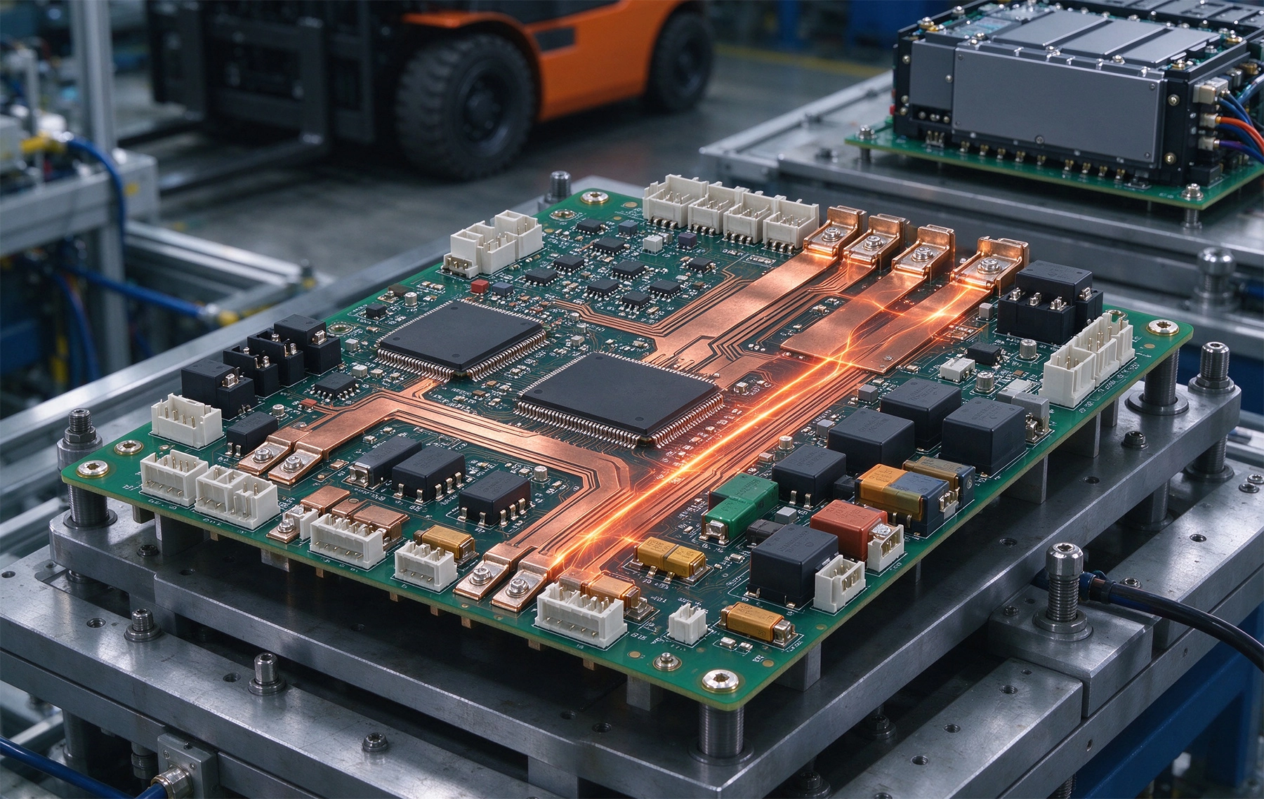
Electric forklifts are not your average consumer electronics. They operate in harsh environments—dusty warehouses, cold storage facilities, and outdoor yards. The Power Electronics must handle continuous high loads during lifting operations and regenerative braking energy when lowering loads.
Typically, the main inverter board or the motor driver in a forklift handles currents ranging from 100A continuous to peaks of 500A or more. This dictates that your High Current PCB Design for Electric Forklifts must prioritize low resistance paths to minimize I²R losses. Every milliohm of resistance counts because that lost energy turns directly into heat, which is the enemy of reliability.
The first thing you look at is the copper. Standard 1oz or 2oz copper is rarely enough for the main power rails in a forklift controller. You are likely looking at 4oz, 6oz, or even 10oz copper weights. But simply increasing Copper Weight isn't a magic bullet; it introduces manufacturing challenges like undercutting during etching.
When calculating trace width, you must use the Ipc-2221 standards but apply a conservative derating factor. I always recommend aiming for a temperature rise of no more than 10°C to 20°C above ambient. If your trace gets too hot, you risk delaminating the FR4 substrate or damaging nearby components.
Here is a quick rule of thumb I use: for external layers carrying 100A with a 20°C rise, you need a significant cross-sectional area. Often, it is better to use busbars or heavy coin inserts for the main power paths rather than relying solely on Pcb Traces. This is a crucial strategy in effective High Current Pcb Design for Electric Forklifts.
Sometimes, the Pcb Trace Width required is physically impossible within your enclosure. In these cases, integrating copper busbars or "copper coins" embedded in the PCB is the way to go. This allows you to carry massive current through a small footprint while using the metal mass as a heatsink.
Heat Dissipation is the second biggest challenge after conductivity. In a sealed IP65 enclosure typical for forklift electronics, convection cooling is limited. You have to rely on conduction.
Thermal Vias: Don't just place one via; use arrays. Stitching vias under power components (like MOSFETs or IGBTs) help transfer heat to internal ground planes or bottom-layer heatsinks. However, be careful with via tenting. If you are using heavy soldering processes, you want to ensure the vias are plugged or filled to prevent Solder Wicking away from the component pads.
Substrate Selection: Standard FR4 has a thermal conductivity of about 0.3 W/mK. For high-power density areas, consider Metal Core PCBs (MCPCB) or ceramic-filled laminates which offer much better thermal performance. Although, for the main logic boards of forklifts, Heavy Copper FR4 is usually the industry standard due to cost and multilayer capabilities.
Selecting the right components is half the battle. For the switching elements, SiC (Silicon Carbide) MOSFETs are becoming popular in forklift inverters due to their high efficiency and switching speed. However, they run hot and require careful gate drive layout.
Placement Tips:
Designing the board is one thing; building it is another. Not all PCB manufacturers can handle 6oz or 10oz copper with fine pitch components. You need to communicate clearly with your fabricator.
Solder Mask and Surface Finish: With high currents, the solder mask acts as a thermal insulator. Sometimes, designers leave the high-current traces exposed (with solder plating) to add more solder during assembly, effectively increasing the cross-section. Enig (Electroless Nickel Immersion Gold) is a common finish, but for high-current soldering areas, Hasl (Hot Air Solder Leveling) or thick silver plating might be better to handle the thermal stress of assembly.
Also, consider the mechanical strength. Electric forklifts vibrate. Heavy components like large capacitors and busbars need mechanical anchoring or adhesive support to prevent fatigue failure of the solder joints.
Designing for industrial EVs is tough. It requires a balance of Electrical Engineering, thermal physics, and mechanical common sense. By focusing on Heavy Copper, robust thermal paths, and strict adherence to safety standards, you can create a reliable controller. Remember, in High Current Pcb Design for Electric Forklifts, there is no room for "good enough"—it has to work when the warehouse is busy and the heat is on.
If you are starting a new project, I suggest prototyping with thermal imaging early on. You will be surprised where the hotspots hide.
While it depends on the current, typically 4oz to 6oz is standard for main power rails. For lower current control signals, 1oz is fine.
Avoid using standard thermal relief spokes for high current connections as they increase resistance. Use direct connections or massive copper pours, but be aware this makes soldering harder.
Yes, provided you manage the temperature rise. If the board exceeds the Tg (Glass Transition Temperature) of the FR4 (usually around 130°C-150°C), the board can delaminate. Keep your design cool.
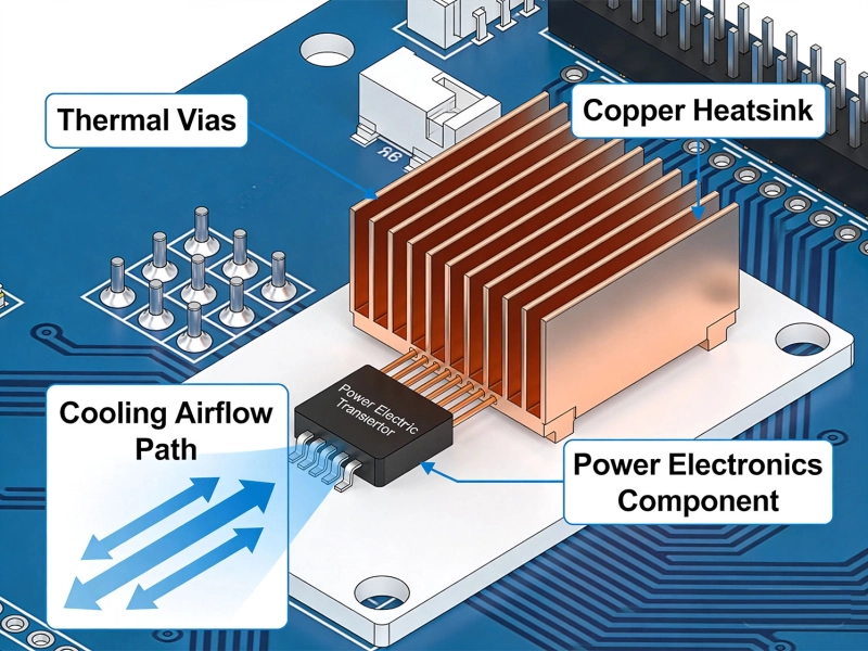
Why Your High-Power PCBs Overheat (And the 5 Methods That Actually Fix It)May/20/2026
High Current PCB Design for Electric Vehicle Charging StationsAugust/15/2026
High Current PCB Thermal Relief: Full Connect vs. Modified SpokesJuly/16/2026
High Current PCB Design for Railway Traction SystemsAugust/07/2026
High Current PCB Trace Width Calculator: The Ultimate Engineering GuideMay/20/2026
Designing a High Current PCB Motor Driver: Avoiding EMI PitfallsJuly/14/2026
High Current PCB Design for Aerospace Power DistributionSeptember/08/2026
High Current PCB Design for Marine Battery SystemsSeptember/21/2026