

Marine battery systems operate in some of the most demanding environments in electronics. Whether powering electric ferries, offshore supply vessels, or recreational boats with advanced navigation systems, these battery banks must deliver high currents reliably while withstanding salt air, vibration, moisture, and Thermal Cycling. The PCBs that manage this power flow face design challenges that differ substantially from standard industrial or consumer applications. Engineers who understand these unique requirements create systems that perform safely and last through years of harsh marine service.
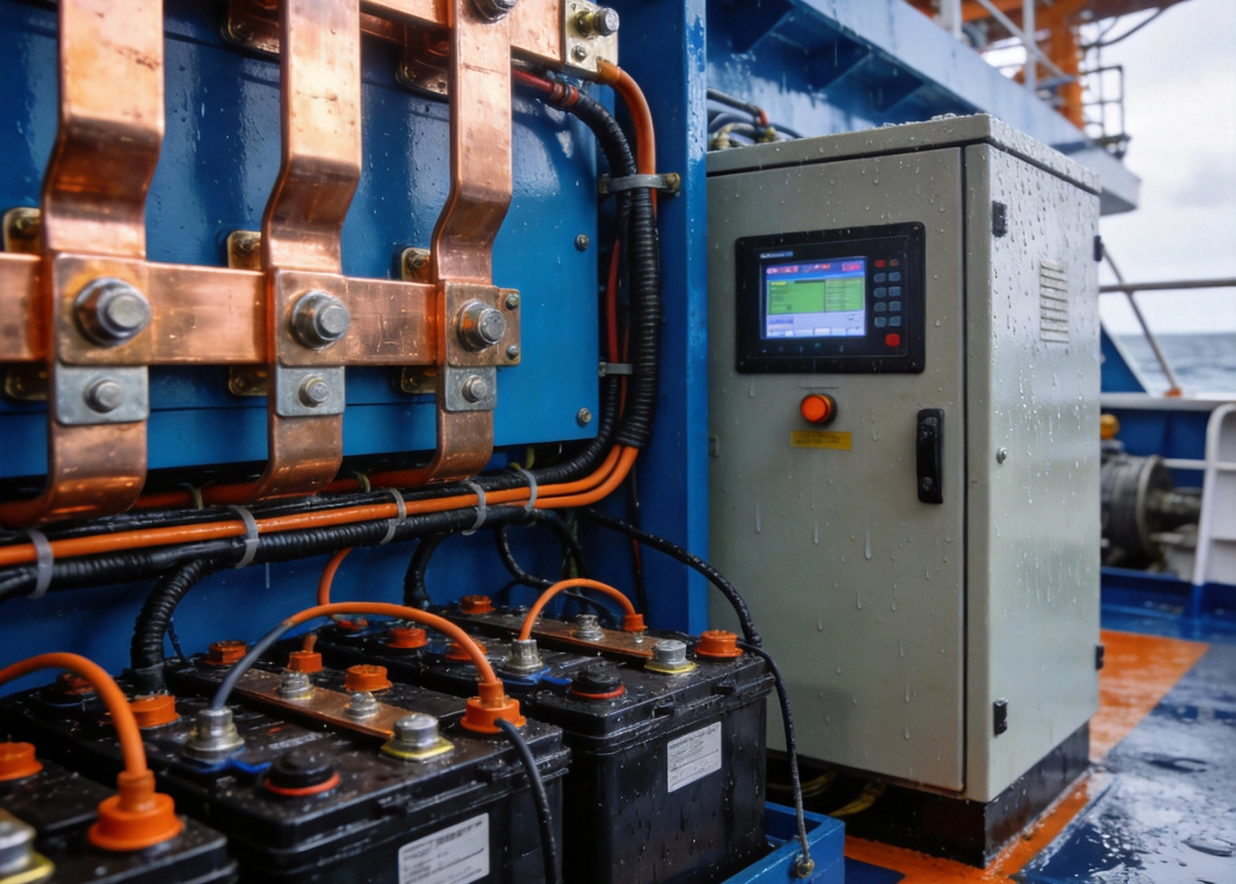
Marine battery applications span a wide range of current requirements depending on the system architecture. A small trolling motor might draw 50-100 amps, while large vessel propulsion systems can require thousands of amps during peak demand. Battery management systems (BMS) that monitor and control these loads must handle substantial currents while maintaining precise measurement accuracy for state-of-charge calculations.
The transition to lithium-ion batteries in marine applications has intensified current demands further. Unlike lead-acid batteries with gradual voltage decline, lithium-ion systems maintain near-constant voltage until nearly depleted, causing current draw to remain high throughout the discharge cycle. This characteristic demands PCB designs that can handle sustained high currents without thermal runaway or connection degradation.
Marine applications often involve sustained high-current operation rather than brief pulses. A vessel operating at full propulsion power draws continuously for hours, unlike automotive applications with intermittent load profiles. This continuous current demands PCB designs with superior Thermal Management capabilities and connection methods that will not degrade over extended high-temperature operation.
Cranking current for engine starting presents another challenge, with brief peaks potentially exceeding five times normal operating current. PCBs serving starter circuits must accommodate these transient loads without triggering thermal protection or causing connection fatigue. Careful attention to connection design and thermal mass helps absorb pulse energy without adverse effects.
Standard PCB copper weights of 1-2 oz per square foot cannot support the current levels required in marine battery systems. High Current designs typically require 3-10 oz copper, with some applications needing custom processes for 20 oz or heavier plating. This Heavy Copper serves dual purposes: conducting current with minimal resistive heating and providing thermal mass to absorb heat generated at connections and semiconductor devices.
Trace width calculations for High Current designs follow Ipc-2152 standards, which provide guidance for current-carrying capacity under various conditions. However, these standards assume relatively constant temperatures and may underestimate requirements for components with restricted thermal paths. Experienced designers add safety margins of 30-50% beyond calculated minimums to account for real-world marine operating conditions.
For a 100-amp continuous current requirement with 4 oz copper, trace width calculations suggest approximately 150 mils (3.8mm) per conductor assuming external traces and adequate thermal dissipation. However, inside an enclosed marine junction box with limited airflow, this width may need to increase substantially. Temperature rise limits of 10-20°C above ambient guide these decisions, with lower rises preferred for longer service life.
The relationship between Copper Weight and current capacity is not linear. Doubling Copper Weight does not double current capacity because Thermal Resistance to the ambient environment remains largely unchanged. Instead, heavier copper provides lower resistance and reduced resistive heating, with the primary benefit being improved thermal dissipation from the lower temperature rise.
Heavy Copper PCBs require specialized plating processes to achieve uniform coverage in vias and on trace surfaces. Standard plating processes may leave thin spots at via walls or trace corners, creating hot spots that accelerate degradation. Manufacturers experienced in heavy copper work use pulse plating and specialized chemistry to achieve consistent 1-mil minimum plating thickness throughout the board.
Surface finish selection affects both solderability and contact resistance. Heavy silver or tin plating provides excellent conductivity for press-fit connections, while ENIG (electroless nickel immersion gold) offers superior flatness for fine-pitch control circuits. Many marine high-current boards use selective plating to apply expensive finishes only where needed, with heavy tin plating protecting high-current bus structures.
Heat represents the primary enemy of high-current marine Pcb Reliability. Current flowing through resistance generates heat according to the power equation (I²R), meaning small increases in current produce large increases in heating. A doubling of current quadruples power dissipation, making Thermal Management essential for any marine battery PCB handling significant power.
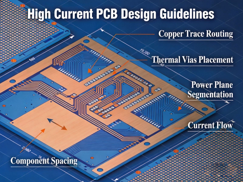
Thermal Vias connect current-carrying traces to internal or external ground planes that serve as Heat Sinks. These vias must be properly sized and populated to transfer heat efficiently without compromising current capacity. A common approach places Thermal Vias beneath MOSFETs and other semiconductor devices, with the board mounting pattern forming a thermal connection to an external heatsink or the system chassis.
Marine battery management PCBs often mount directly to heatsinks using thermal interface materials (TIM). These materials fill microscopic gaps between the PCB and metal heatsink surface, improving thermal conductivity from the board to the cooling structure. Standard TIM materials offer thermal conductivity of 1-10 W/mK, while premium thermal gap fillers can exceed 5 W/mK for demanding applications.
The PCB mounting method affects both thermal and electrical performance. Screw-mounted assemblies with spring clips provide consistent pressure that maintains thermal contact over the product lifetime. Adhesive-mounted assemblies offer simpler installation but may delaminate over thermal cycles. Many marine designs use both adhesive and mechanical fastening to ensure long-term reliability.
Some marine battery systems incorporate forced-air or liquid cooling to manage high current heating. When active cooling is available, PCB designers can reduce copper weights and trace widths somewhat, relying on airflow or coolant circulation to remove heat. However, marine environments make active cooling challenging due to salt air corrosion and the difficulty of maintaining cooling systems on vessels.
Sealed enclosures with passive cooling remain common in marine applications for good reason. These systems require no maintenance, contain no moving parts prone to failure, and avoid corrosion issues associated with cooling air intakes in salt environments. Designing PCBs for sealed enclosure operation means planning for worst-case ambient temperatures with generous thermal margins.
The connection between heavy cables and Pcb Traces often limits system reliability more than the PCB itself. Terminal blocks rated for marine current levels provide secure connections, but terminations require careful attention to torque specifications and periodic inspection. Vibration and Thermal Cycling can loosen connections over time, creating resistance increases that generate heat and potential safety hazards.
Bus Bar integration offers superior current-carrying capability compared to Pcb Traces alone. Solid copper bars can be bolted directly to PCB termination points, distributing current across multiple connection points and providing substantial thermal mass. Some designs incorporate bus bars as integral board features, with the PCB substrate providing mechanical support and insulation while copper bars carry the primary current.
Press-fit terminals provide gas-tight connections between PCB through-holes and component leads without soldering. This technology works well for high-current applications because the spring pressure connection maintains contact integrity despite thermal cycling. The gas-tight interface prevents the oxidation that gradually increases resistance in bolted connections.
Multi-pin press-fit connectors can replace traditional Bus Bar terminations for applications requiring disconnection for service. Heavy-duty industrial connectors rated for marine use provide IP67 or better sealing against moisture ingress. These connectors simplify field service while maintaining the reliability essential for marine systems where failure may strand vessels.
Cable terminations to high-current PCBs require proper preparation to ensure reliable connections. Cable lugs must match the terminal block specifications, with appropriate stud size and lug angle. Crimping quality directly affects connection resistance, making proper crimp tooling essential for high-current applications.
Anti-oxidant compounds applied to terminations before assembly slow corrosion in salt air environments. These compounds displace moisture and maintain low-resistance contact at the termination interface. Regular inspection and re-torquing of cable terminations should be part of vessel maintenance schedules, particularly in the first year after installation when initial settling may cause connection relaxation.
Marine battery systems present inherent safety risks that must be addressed in Pcb Design. Battery cells can deliver extraordinary short-circuit currents capable of causing fires or explosions if protective measures fail. Fusing, current monitoring, and controlled shutdown sequences protect both equipment and personnel from these hazards.
Solid-state protection circuits using MOSFETs as electronic switches provide fast response to overcurrent conditions. These circuits sense current through shunt resistors and open the MOSFET within microseconds when current exceeds limits. However, the MOSFET must be properly sized for the prospective short-circuit current, which in large marine battery systems can reach tens of thousands of amps.
Marine electrical systems often use negative-ground architecture, but this varies by vessel and application. PCBs serving marine battery systems must accommodate the grounding scheme of the intended installation, with clear documentation of applicable configurations. Incorrect grounding can cause protection circuits to malfunction or create safety hazards during fault conditions.
Galvanic isolation between battery management circuits and vessel communication networks prevents ground loops and protects sensitive electronics from high voltage transients. Optical isolators and isolated DC-DC converters provide this isolation while maintaining signal integrity for monitoring and control functions. The isolation barrier must withstand the voltage differences that occur during battery charging and discharging cycles.
Modern marine battery systems include extensive monitoring for state-of-charge, cell temperatures, and system health. The PCB must integrate high-accuracy analog measurement circuits with robust digital communication to vessel navigation and control systems. This integration requires careful attention to noise immunity and signal routing to prevent measurement errors from switching transients in power circuits.
CAN bus and NMEA 2000 interfaces connect battery management systems to vessel displays and controls. The PCB physical layer must meet these standards for EMC immunity in the electrically noisy marine environment. Shielded twisted-pair routing and proper termination prevent communication errors that could cause incorrect operator information during critical operations.
The marine environment attacks electronics relentlessly through salt air, moisture, and temperature extremes. PCBs serving battery systems must incorporate protection measures that maintain reliability over years of exposure. Conformal coating provides a basic moisture barrier, while full encapsulation offers superior protection for the most demanding applications.
IP67-rated enclosures provide a first line of defense, but enclosure seals degrade over time and require periodic inspection. PCB-level protection ensures that temporary enclosure breaches do not cause immediate failure. Premium marine electronics manufacturers often use both enclosure sealing and PCB coating to achieve defense-in-depth against environmental damage.
Acrylic conformal coatings offer easy application and reworkability at moderate cost, making them popular for marine applications where field repair capability is desired. Urethane coatings provide superior chemical resistance and mechanical protection but require more aggressive stripping for rework. Silicone coatings excel in high-temperature environments but may trap moisture if applied over contaminated surfaces.
Application method affects coating quality and protection level. Spray application provides even coverage but may leave thin spots in shadowed areas. Dip coating achieves thorough coverage but requires masking of connectors and terminals. Selective coating systems using robotic dispensers apply precise coating thickness exactly where needed, eliminating masking requirements while ensuring complete coverage.
Heavy Copper Pcb manufacturing requires specialized processes that not all manufacturers can provide reliably. Finding a manufacturer experienced in marine and transportation electronics ensures familiarity with the quality systems and documentation requirements these applications demand. IATF 16949 certification indicates automotive-quality processes, while marine-specific standards like DNV-GL provide additional validation of manufacturing capability.
Thermal cycling testing during qualification validates that PCB constructions will survive marine service conditions. Accelerated aging protocols simulate years of thermal cycling in compressed timeframes, identifying construction weaknesses before production deployment. These tests particularly expose via barrel fatigue and solder joint issues that might not appear for months in actual service.
Marine regulatory requirements often mandate documentation of Pcb Manufacturing processes and material traceability. Certificates of conformance, material data sheets, and process records must be maintained and available for inspection. PCB manufacturers serving marine markets maintain quality management systems that generate this documentation automatically as part of their production records.
First Article Inspection (FAI) documentation verifies that initial production runs match design specifications before full production approval. This documentation provides confidence that manufacturing processes are properly established and will produce consistent results throughout the production run. Marine certification bodies may require FAI documentation as part of type approval processes.
High Current PCB design for marine battery systems demands attention to thermal management, connection reliability, environmental protection, and manufacturing capability that exceeds standard electronic design practices. The combination of sustained high currents, harsh marine environment, and safety-critical operation creates requirements that reward careful engineering and penalize shortcuts.
Successful marine battery management PCBs begin with accurate current calculations that include appropriate safety margins for sustained operation and transient peaks. Thermal Design must anticipate worst-case ambient temperatures within sealed enclosures, with copper weights and heatsinking sized accordingly. Connection methods must survive years of vibration and thermal cycling without degradation. Protection circuitry must respond faster than human operators can react, providing autonomous safety backup for critical systems.
Working with experienced manufacturers who understand marine requirements ensures that designs translate reliably into production. The investment in proper qualification and documentation pays dividends through reduced field failures, simpler regulatory approval, and satisfied customers whose vessels operate reliably season after season.
Designing a 100A High Current PCB for EV Battery Management SystemsJuly/09/2026
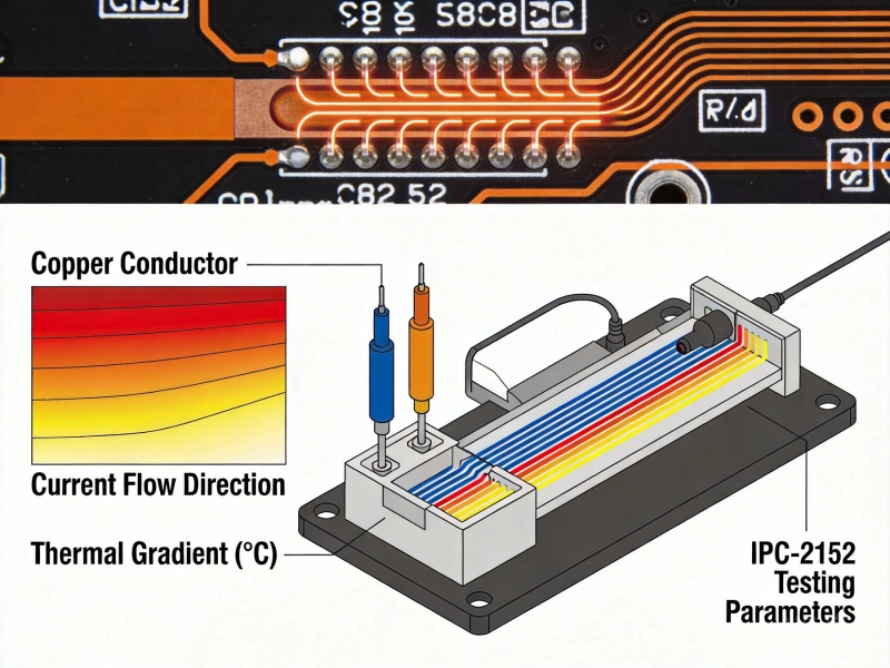
IPC-2152 Current Carrying Capacity Calculation GuideJune/03/2026
High Current PCB Design for High-Frequency Switching RegulatorsSeptember/04/2026
Designing a High Current PCB for Industrial Welding EquipmentJuly/23/2026
High Current PCB Design for Aerospace Power DistributionSeptember/08/2026
2oz vs. 4oz Copper: Which is Best for Your High Current PCB?July/10/2026
High Current PCB Pad Design: Reinforced Plating vs. Standard PadsJuly/28/2026
High Current PCB Design GuidelinesMay/21/2026