

Electric boats are no longer a niche concept. From quiet river tour vessels and personal watercraft to small commercial freighters operating on inland waterways, electrification is reshaping maritime propulsion. The engineering challenge is substantial: a boat Motor Controller must handle hundreds of amperes in a wet, vibration-prone, salt-corrosive environment while maintaining high efficiency and reliable protection. The printed circuit board at the heart of that controller is where the hardest design decisions live.
Unlike low-power signal boards, a high-current propulsion PCB has to manage thermal dissipation, voltage drop, inductance, and mechanical robustness simultaneously. Getting any one of those wrong produces a failure — either immediate (fried MOSFETs, welded relay contacts) or gradual (junction fatigue, creeping resistance, insulation breakdown in a humid marine environment). This article walks through the key design considerations that determine whether an electric boat Power Electronics assembly survives its first season or its tenth.
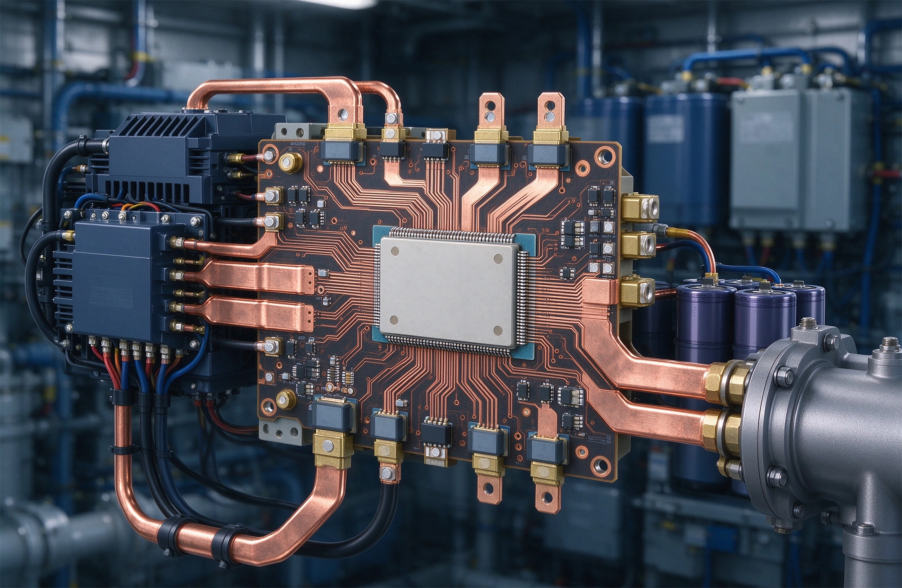
Electric boat propulsion systems typically operate at two voltage tiers. Small recreational boats — electric outboards for kayaks, small sailboats, tenders — run on 12 V to 48 V systems delivering 1 kW to 10 kW. Medium-sized commercial vessels — tour boats, ferries, work skiffs — use 72 V to 400 V systems in the 20 kW to 200 kW range. The PCB designer needs to work within both tiers, but the board-level engineering challenges scale non-linearly with current.
Ohm's law is unforgiving at High Current. A trace carrying 100 A at 48 V that drops just 0.5 V across a poorly designed power bus has already consumed 1% of the total system voltage headroom — and that trace is also dissipating 50 W of heat along the way. At 200 A and above, even short runs of undersized copper become thermal liabilities that force active cooling or force the designer into more expensive busbar and substrate solutions.
The Motor Controller itself is almost always a three-phase inverter bridge — six MOSFETs or IGBTs arranged in an H-bridge configuration, switching at frequencies typically between 8 kHz and 20 kHz. The switching frequency is a design trade: higher frequencies reduce motor acoustic noise and allow smaller filtering components, but they increase switching losses and generate more Emi, which matters enormously in a marine environment where radio communication, chart plotters, and fish finders are present.
The starting point for any high-current power board is adequate conductor cross-section. Ipc-2152 provides the most widely referenced guidance for current-carrying capacity in printed boards, and it supersedes the older Ipc-2221 charts for most modern design work. The standard accounts for conductor width, thickness (Copper Weight), temperature rise above ambient, and whether the conductor is on the surface or internal.
For electric boat applications, surface traces handling 50 A or more almost always require Heavy Copper — 2 oz/ft² (70 μm) minimum, and 3 oz/ft² (105 μm) or heavier for currents above 100 A. At 3 oz copper, a 10 mm wide trace on the surface can carry roughly 35–40 A with a 10 °C temperature rise. Getting to 100 A requires either very wide traces — impractical on a typical PCB — or the use of additional copper layers in parallel, busbars soldered to the board surface, or wire-bonded heavy-gauge leads.
Practical tip: do not try to carry 100 A on a single 10 mm surface trace. Instead, distribute the current across multiple parallel traces on adjacent layers connected by multiple vias, or use a soldered-on copper busbar that bolts directly to the PCB pad. The busbar approach is common in commercial motor controller modules and is worth the mechanical complexity for anything above roughly 60 A continuous.
Heat generated in power semiconductors — MOSFETs, IGBTs, gate drivers — must find a path to ambient. The most effective first step is a Thermal Via Array under the device's exposed pad or thermal tab. These vias should be as large as the fab allows — typically 0.3 mm to 0.5 mm diameter — and plated with as much copper as possible to maximize thermal conductivity from the device through the board to an internal ground plane or bottom-side heatsink.
Thermal via arrays under a MOSFET's drain tab are not just about conduction — they also help with current spreading. The copper in the via barrels effectively distributes the Current Density over a wider area before it enters the plane layer, reducing Current Crowding at the package perimeter.
Natural convection is rarely sufficient for propulsion-level power densities. Most commercial electric boat controllers use aluminum heatsinks either bonded to the PCB or mounted as a separate structure with thermal interface material (TIM) between the semiconductor and the metal. Forced airflow — whether passive chimney convection or an active fan — increases the heatsink's effectiveness significantly and is standard in controllers rated above 5 kW.
The marine environment adds a wrinkle: salt spray and humidity accelerate corrosion on aluminum heatsinks, especially if the boat spends time sitting at anchor in a damp marina. Anodized aluminum heatsinks or sealed (conformal-coated) assemblies are preferable for salt-water exposure, and the thermal interface material should be rated for the full temperature range the boat will encounter — including direct sun exposure on a deck in summer.
A solid internal ground or power plane does more than distribute voltage and ground reference — it also acts as an isothermal spreading layer. By routing heat laterally from the semiconductor to cooler regions of the board, internal planes reduce the local hot-spot temperature and extend the life of the switching devices. The plane should be continuous and unbroken in the area under the power stage, with Thermal Vias stitching the surface device to the internal plane at regular intervals.
High-current switching generates rapid current slew rates — di/dt — that interact with parasitic Loop Inductance to produce voltage overshoot across the switching devices. In a 400 V system switching 200 A at a 10 kHz rate, a 10 nH of parasitic Loop Inductance produces roughly 200 V of overshoot, which can destroy a MOSFET rated for 650 V in a single pulse.
Minimizing this inductance is one of the most critical layout objectives in a propulsion inverter. The key strategies are well-established in Power Electronics but demand discipline in the physical layout:
For boards where layout constraints force longer connections, adding RC snubber networks (typically 0.1 μF to 1 μF ceramic in series with a low-inductance resistor) across each switching node and the DC link rails absorbs some of the energy from the voltage spike and protects the semiconductor.
The power stage is only as good as the signal that drives it. Gate drive circuits for MOSFETs and IGBTs in a three-phase inverter need to deliver fast, clean transitions — typically 20 ns to 50 ns rise and fall times — to minimize switching losses. At the same time, the gate drive loops must be isolated from the high-voltage motor bus to protect the control logic and the operator.
Isolation is typically achieved using optocouplers or isolated gate driver ICs with transformer isolation. The Creepage And Clearance distances required depend on the system voltage: for a 400 V bus, Ipc-2221 generally requires at least 3.2 mm of creepage along the board surface and 1.5 mm through air between primary and secondary-side circuits. Failure to observe these clearances creates a safety hazard for anyone who might touch the enclosure during operation.
Kelvin source connections — separating the gate drive return from the power loop source return — are important at high switching currents. The voltage drop across the common source inductance when the MOSFET turns on can reduce the gate-to-source voltage and slow the switching transition, increasing losses and potentially causing shoot-through in the half-bridge. A dedicated sense pin on the gate driver connected directly to the MOSFET source lead, separate from the power loop, helps maintain clean switching at high di/dt.
Every electric boat propulsion controller needs robust overcurrent protection. Shunt resistors in the DC link — typically 50 μΩ to 200 μΩ — provide a measurable voltage drop proportional to current that the control processor monitors in real time. The voltage across a 100 μΩ shunt carrying 200 A is only 20 mV, which demands careful analog design: the sense amplifier must have low offset voltage and adequate common-mode rejection, and the sense traces must be Kelvin-connected directly to the shunt pads to avoid including the voltage drop in the connecting leads.
Short circuit protection — the ability to detect and interrupt a catastrophic fault within microseconds — typically uses the MOSFET's on-resistance (RDS_on) as the current sense element rather than a shunt. The controller senses the voltage across the low-side MOSFET during the fault event and trips when that voltage exceeds a threshold. This approach eliminates the extra shunt component but places demanding requirements on the desaturation detection circuit and the gate driver desat protection pin.
Electric motors are inductive loads, and when the controller cuts off current to the motor windings, the collapsing magnetic field generates a voltage spike that can exceed the MOSFET blocking voltage. In a 48 V system, this flyback voltage can easily reach 100 V or more. Transient voltage suppression (TVS) diodes — typically unidirectional TVS diodes rated at 1.5x the system voltage — should be placed across the motor phase leads and the DC input to clamp these spikes before they damage the switching devices.
Marine battery systems are routinely connected and disconnected under load, and polarity reversal during battery hookup is a real-world occurrence that destroys unprotected controllers instantly. A reverse-polarity protection diode or MOSFET-based ideal diode in the DC input rail prevents this failure mode. The voltage drop across the protection device must be accounted for in the power budget — at 200 A, even a 0.5 V drop across a protection diode represents 100 W of dissipation — which often makes a MOSFET-based solution preferable to a conventional diode.
Standard FR-4 is adequate for lower-power motor controllers up to roughly 5 kW, but above that power level the thermal demands push designers toward higher-grade materials. High-Tg FR-4 (Tg ≥ 150 °C) provides better resistance to thermal delamination during multiple thermal cycles and is the minimum recommendation for any propulsion-grade board. For 400 V systems and above, or where extended temperature range is needed, polyimide (Kapton-based) or alumina Ceramic Substrates offer better thermal conductivity and voltage breakdown resistance than FR-4.
The marine environment — salt spray, humidity, occasional immersion if the hull is compromised — demands conformal coating on any electronics that is not already enclosed in a sealed housing. Acrylic conformal coatings are cost-effective and easy to repair, but they offer limited chemical resistance in salt-water environments. Urethane and silicone coatings provide better long-term protection in marine service, with silicone offering the best flexibility for boards that experience Thermal Cycling.
For fully submerged or regularly splashed applications, potting the entire controller assembly in epoxy or polyurethane compound is more reliable than conformal coating alone. Potting adds weight and makes field repair impractical, so the tradeoff between protection level and serviceability must be considered at the system design stage.
High-current power connections on the PCB should use threaded terminals, heavy-gauge ring lugs, or compression-mount busbars rather than spring-loaded connectors. Vibration in a boat hull — from wave impact, motor operation, and hull flexing — can work loose any connector that relies on normal force contact. Anderson Powerpole-style connectors are widely used in electric boat battery and controller interconnects because they handle High Current reliably and are easy to service in the field.
Designing a High-current Pcb for electric boat propulsion is an exercise in managing tradeoffs across thermal, electrical, and mechanical domains simultaneously. The board that works beautifully in a lab bench test can fail within months in a vibrating hull repeatedly exposed to saltwater spray. That is why the best designs start from the operating environment and work backward: choosing materials for marine durability, sizing traces and heatsinks for worst-case thermal conditions, adding protection circuits for the fault scenarios that happen in the real world, not just in the simulation.
The good news is that the core engineering principles are well-established — IPC standards, proven switching topologies, thermal modeling tools — and applying them systematically to the marine context produces reliable controllers that last. The bad news is that there are no shortcuts: skimping on copper weight, ignoring loop inductance, or omitting protection circuits will surface as a field failure at the worst possible moment, miles from shore.
Contact us to discuss your requirements.
Mastering IPC-2152 Current Carrying Capacity Calculation for Reliable PCB DesignJune/04/2026
High Current PCB Design for High-Power LED DriversAugust/12/2026

High Current PCB Design for Railway Traction SystemsAugust/07/2026

High Current PCB Design for Data Center Power ShelvesOctober/19/2026

Designing a High Current PCB for Industrial Welding EquipmentJuly/23/2026
High Current PCB Current Sensing: Shunt Resistor vs. Hall Effect LayoutJuly/29/2026
High Current PCB Design for High-Frequency Switching RegulatorsSeptember/04/2026

High Current PCB Design for Electric Forklifts: A Practical Engineering GuideOctober/13/2026