

When Power Electronics push beyond 50 A, 100 A, or even several hundred amperes, the Copper Thickness alone cannot guarantee long-term reliability. Heavy Copper traces reduce resistance and improve heat spreading, but connectors, busbars, large power terminals, and heavy components still create concentrated mechanical and thermal loads. This is where High Current PCB stiffeners become essential. They reinforce critical zones, reduce flex under insertion force, and help spread heat away from high-power interfaces.
In real manufacturing and assembly projects, many field failures do not come from a weak trace. They come from a weak interface. A heavy Copper Trace may be perfectly sized, yet the pad near a high-current connector can crack after repeated mating cycles, vibration, or Thermal Cycling. Adding the right stiffener material, in the right location, with proper thermal and DFM planning, can prevent these problems before the board enters production.
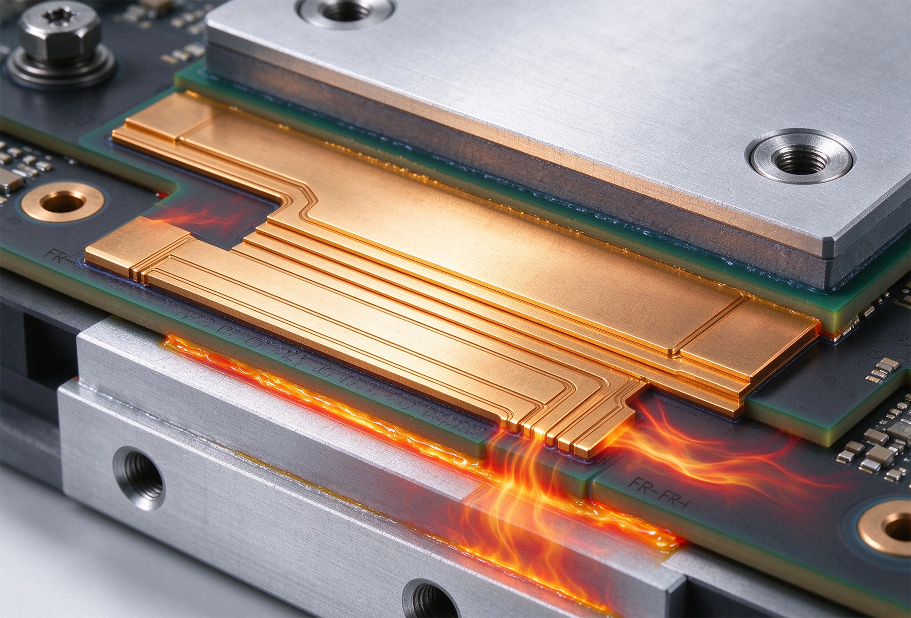
A High Current PCB stiffener is a localized reinforcement added to a printed circuit board to improve mechanical rigidity and thermal stability in high-stress areas. Unlike a full metal-core base, a stiffener is usually applied only where it is needed, such as near connectors, power terminals, busbar mounting points, heavy transformers, or large heat-generating components.
Stiffeners are especially common on flexible and rigid-flex boards, but they are also relevant for Heavy Copper rigid boards that must support high insertion forces or external mechanical loads. Typical stiffener materials include FR-4, polyimide, stainless steel, and aluminum. Each material brings different trade-offs in rigidity, thermal conductivity, weight, cost, and manufacturability.
For High Current designs, the stiffener is not only a mechanical part. It also becomes part of the thermal path. Aluminum and steel stiffeners can conduct heat away from power terminals, while FR-4 and polyimide stiffeners mainly provide structural support without creating unintended thermal shorts.
Heavy copper PCBs, typically defined as boards with copper weights of 3 oz/ft² or higher, are chosen for high-current capability, improved thermal spreading, and stronger plated through-holes. Copper has much higher thermal conductivity than FR-4, which helps move heat from hotspots into wider copper areas. However, heavy copper does not eliminate all mechanical risks.
Common failure points include:
A stiffener reduces board deflection under load. It also helps keep solder joints and plated through-holes from absorbing excessive shear stress. In High Current systems, this is important because a cracked via barrel or a fatigued solder joint can increase resistance, raise temperature, and eventually cause intermittent faults.
Thermal Management in heavy copper boards depends on Copper Thickness, copper area, via design, and substrate selection. Thick copper layers act as lateral heat spreaders, lowering local temperature rise under continuous load. But heat still needs a path away from concentrated sources such as MOSFETs, IGBTs, shunt resistors, and power connectors.
When a metal stiffener is placed near these areas, it can serve as a passive heat spreader. Aluminum stiffeners are useful when the design needs additional thermal mass and moderate conductivity. Steel stiffeners provide very high rigidity and can also help distribute heat, although their thermal conductivity is lower than copper or aluminum. For designs where electrical isolation is critical, FR-4 or polyimide stiffeners are safer because they do not create unintended conductive paths.
Thermal Vias should be carefully planned when stiffeners are used. If a stiffener covers an area with Thermal Vias, the vias must still be able to transfer heat into internal copper planes or an external heatsink. In some cases, filled and capped vias provide better thermal performance and reduce Solder Wicking during assembly. The stiffener should not block airflow or prevent attachment of external cooling hardware.
High current connectors and busbars create some of the highest mechanical loads on a PCB. Even if the Copper Trace can carry the required current, the mechanical interface may fail first. A stiffener placed under or around the connector increases local board thickness and reduces bending during plug-in, vibration, or cable movement.
For rigid-flex boards, stiffeners are often added beneath connectors to meet insertion force requirements and maintain solder joint integrity. FR-4 stiffeners are common for general mechanical support, while steel stiffeners are used when flatness and rigidity are critical. Polyimide stiffeners are preferred when the board must survive higher assembly temperatures or maintain flexibility outside the reinforced zone.
For rigid heavy copper boards, local reinforcement can be achieved through thicker base material, additional Copper Balancing, strategic stiffener placement, or mechanical mounting features. The goal is to keep stress away from plated through-holes and pad edges. If a connector will be mated many times, the stiffener design should be validated with insertion force testing and thermal cycling.
Choosing a stiffener material requires balancing mechanical strength, thermal performance, manufacturability, and cost.
For High Current Pcb stiffeners used with heavy copper, aluminum and steel are often the most interesting options because they add both mechanical and thermal benefits. However, they also introduce new risks. Metal stiffeners must not create short circuits, interfere with Creepage And Clearance, or trap heat under sensitive components. Isolation layers, keep-out zones, and clear assembly drawings are necessary.
From a manufacturing perspective, stiffeners must be treated as part of the PCB stack-up, not as an afterthought. Early DFM review helps avoid bonding defects, warpage, soldering issues, and thermal bottlenecks.
Key design rules include:
One practical mistake we often see is placing a metal stiffener directly under a Thermal Pad without considering solder flow or electrical isolation. Another is using an overly thick stiffener that makes the local area too rigid, causing stress to move into adjacent flexible zones. Good stiffener design distributes stress instead of concentrating it elsewhere.
High Current Pcb stiffeners are commonly used in systems where heavy copper, high power, and mechanical reliability must coexist.
In these applications, the stiffener often sits at the boundary between electrical performance and mechanical assembly. A well-designed stiffener can reduce connector fatigue, improve thermal stability, and simplify system integration. A poorly designed one can create new failure modes, so verification is essential.
After selecting materials and placing stiffeners, the design should be validated under realistic conditions. Electrical simulation alone is not enough, because mechanical and thermal stresses interact during real operation.
Recommended tests include:
For heavy copper boards, thermal cycling is especially important. Copper and substrate materials expand at different rates, so repeated heating and cooling can create shear stress at interfaces. A stiffener can reduce board-level flex, but it must not increase stress on plated through-holes or create rigid islands that crack under temperature changes.
High current PCB stiffeners are not optional accessories in demanding power designs. They protect connectors, busbars, and heavy components from mechanical fatigue while supporting Thermal Management in heavy copper layouts. The best results come when stiffener material, placement, bonding method, and thermal paths are defined during early Pcb Design, not after the first prototype fails.
For engineers working on Power Electronics, EV systems, industrial drives, or rigid-flex high-current assemblies, stiffeners should be evaluated alongside Copper Weight, via arrays, thermal planes, and assembly constraints. When designed correctly, they improve reliability without adding unnecessary complexity.
A stiffener primarily provides mechanical support, while a heatsink primarily removes heat. However, metal stiffeners such as aluminum or steel can also help spread heat. The two functions can overlap, but they must be designed intentionally.
Yes. FR-4 stiffeners are suitable when the main goal is mechanical reinforcement, especially around connectors. They do not provide significant thermal conduction, so additional thermal vias or copper planes may be needed for heat removal.
They can be safe if proper creepage, clearance, and isolation requirements are met. Metal stiffeners must not reduce electrical spacing or create unintended conductive paths. A detailed mechanical and electrical review is recommended.
Stiffener thickness depends on connector height, insertion force, board flexibility, and enclosure constraints. Common stiffener thicknesses range from 0.2 mm to 2.0 mm, but the final value should be confirmed with the connector datasheet and assembly requirements.
They can. Stiffeners add bonding, alignment, and inspection steps, especially on rigid-flex boards. Early communication with the PCB manufacturer helps avoid delays and ensures the stiffener process matches the assembly method.
High Current PCB Kelvin Connections: Routing Best Practices for AccuracySeptember/09/2026
High Current PCB Failure Modes and PreventionJune/18/2026
Copper Pour vs Trace: What 3 Years of PCB Failures Taught UsMay/21/2026
High Current PCB Design for High-Temperature Downhole ToolsOctober/28/2026
High Current PCB Placed Slots vs. Standard Traces for Extreme CurrentsSeptember/11/2026
High Current PCB Grounding: Star Ground vs. Ground Plane in High Current PathsJuly/31/2026
High Current PCB Solder Wicking: Tented Vias vs. Untented ViasSeptember/01/2026
High Current PCB Design for High-Frequency Switching RegulatorsSeptember/04/2026